Projections
| Site: | WelTec Moodle |
| Course: | Plumbing, Drain-laying and Gas-fitting | Level 3 | 2022 |
| Book: | Projections |
| Printed by: | Guest user |
| Date: | Wednesday, 18 February 2026, 11:43 PM |
Overview
Drawings are representations of ideas 'projected' onto paper or a screen using different types of perspectives.
Here we start to explore how lines become three types of drawings:
- one point perspective
- oblique
- isometic
The isometric perspective is the one most commonly used in trades.
One point perspective
Drawing perspective means drawing what the eye sees. If you stand on railway tracks and look to the horizon the tracks apear to meet. This is one point perspective.
 This link will take you to an activity where you can learn to draw a building.
Key points
- Draw a rectangle to represent a room and another in the centre as a point for the eye to focus on.
- Draw faint lines from corner to corner, so your eyes focus on the middle of the image.
- Draw objects within the room between the crosslines, using the faint lines to guide perspective from the centre point. Everything is drawn to the lines coming from the centre point.
- When you have finished erase the faint guide lines.

Further exploration of one point perspective
If you would like to learn more about drawing using this perspective, you may find these online tutorials useful:
Oblique perspective
If you want to draw a quick sketch of a three dimensional object that is NOT round you can do so using an oblique projection,
Watch the video to learn more about how to use oblique perspective in a drawing.
Select image to view video.
Used with permission of Northern Alberta Institute of Technology.
Key points
Oblique projection is easy and quick to draw so long as the object is not round. This is because you have to 'rotate' the object to get a 3D view. If you do this to a circle shape it will look elliptical not round.
1. Draw the front view.
2. Extend lines back at any angle you like.
3. Draw lines parallel to the lines used in the front view.
Isometic projections
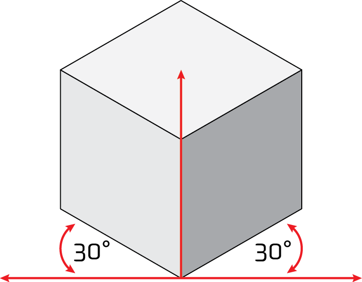
Isometric projection is how we show three dimensions in technical drawings. We can view an object from a side, the front and the top in one drawing.
Isometric perspective uses angles of 30°.
Watch the video to learn more on how to use isometric projection in drawing a rectangular shape.
Select image to view video.
Used with permission of Northern Alberta Institute of Technology.
Third angle view
Creating 3rd angle orthographic projection views from Isometric sketch
Select animation to see how different third angle orthographic views are represented from an isometric sketch.
- Click on each of the 6 views to watch the object rotate to the selected view.
- Click on the icon in the lower right hand corner to reset the view to isometric.
Key points
Isometic projection is the one you are most likely to use.
Definition
A simple way to represent 3D objects in a drawing that shows three views - front, top, side. The verticle lines are vertical, but the horizontal lines are drawn at 30° to the base line.
Remember:
- Everything we make starts as a square or rectangular box that we then 'hack' pieces off to get the shape we want.
- We use isometic projections to show the shape of what we plan to make. We do not manufacture from these drawings, so there are no dimensions. You may use any scale you like.
Rule 1
Draw from the baseline at an angle of 30° on each side of the centre line.

Rule 2
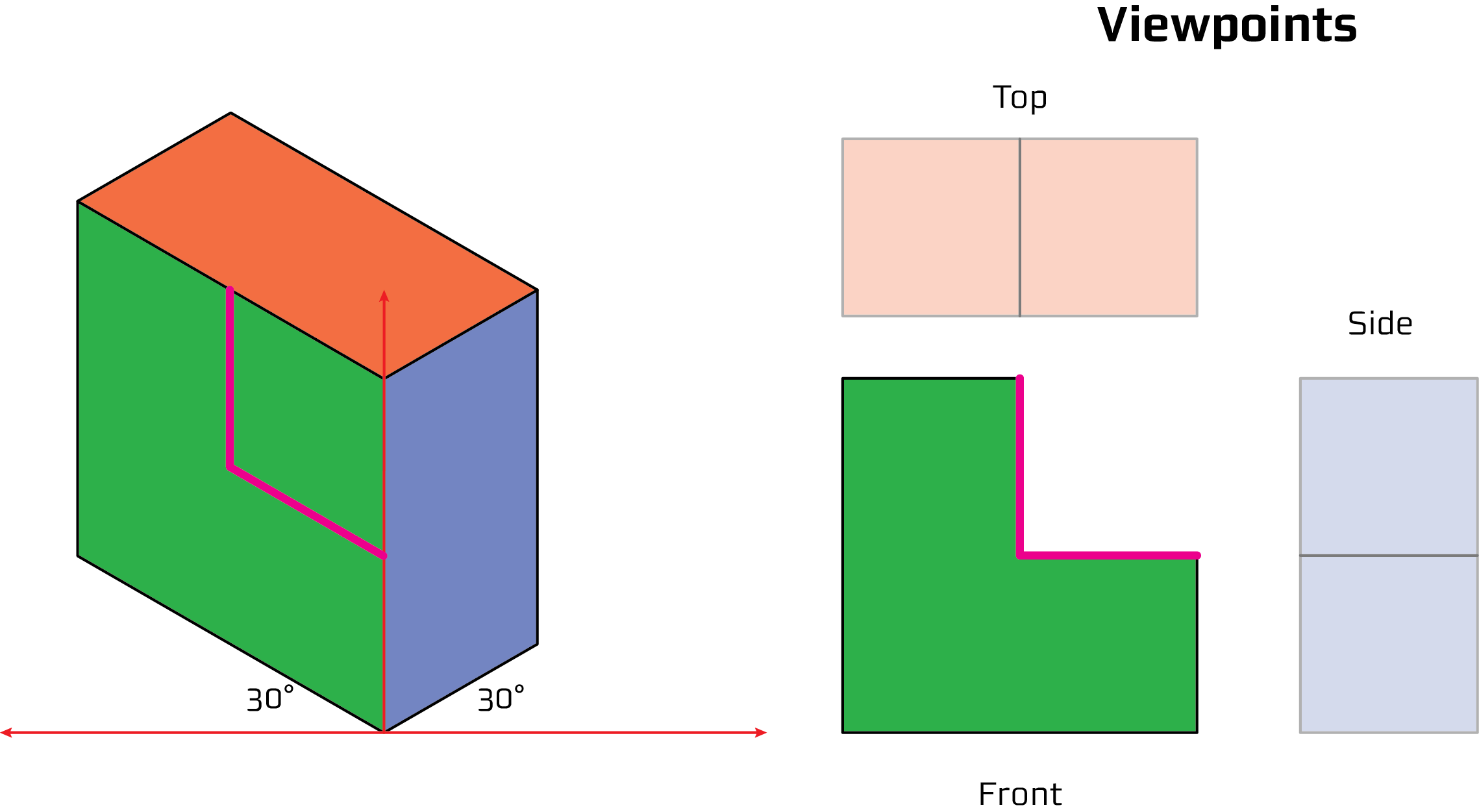
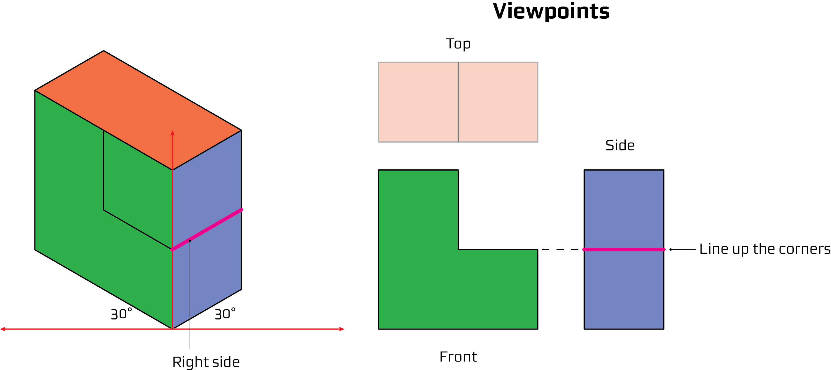
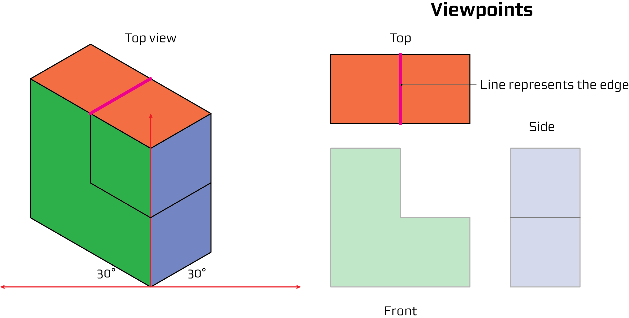
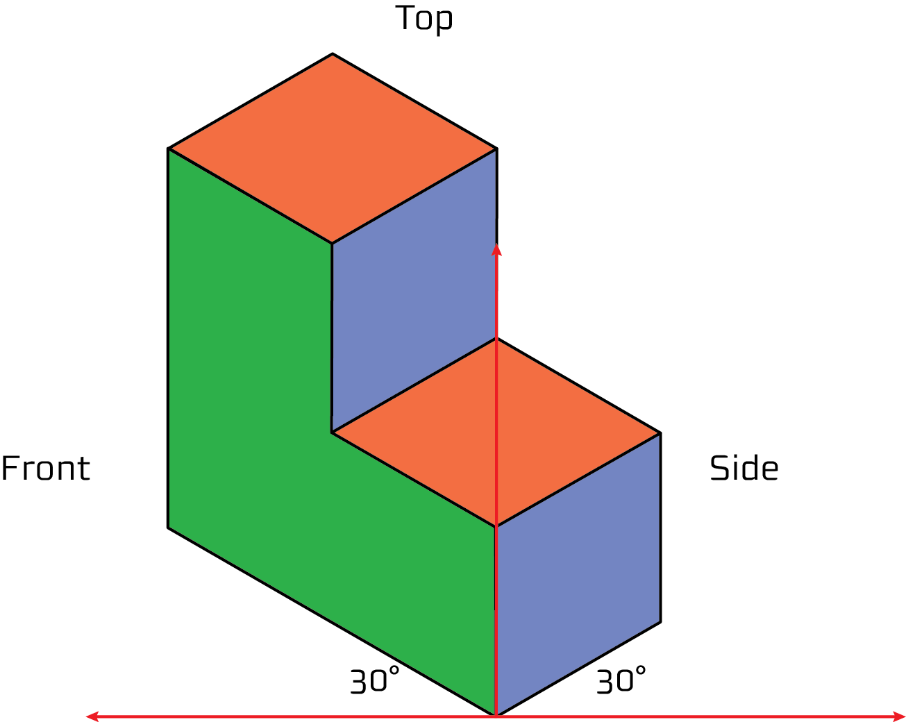
Draw an isometric box. Superimpose the shape you want onto the box. You will need a front view, side view and a top view.
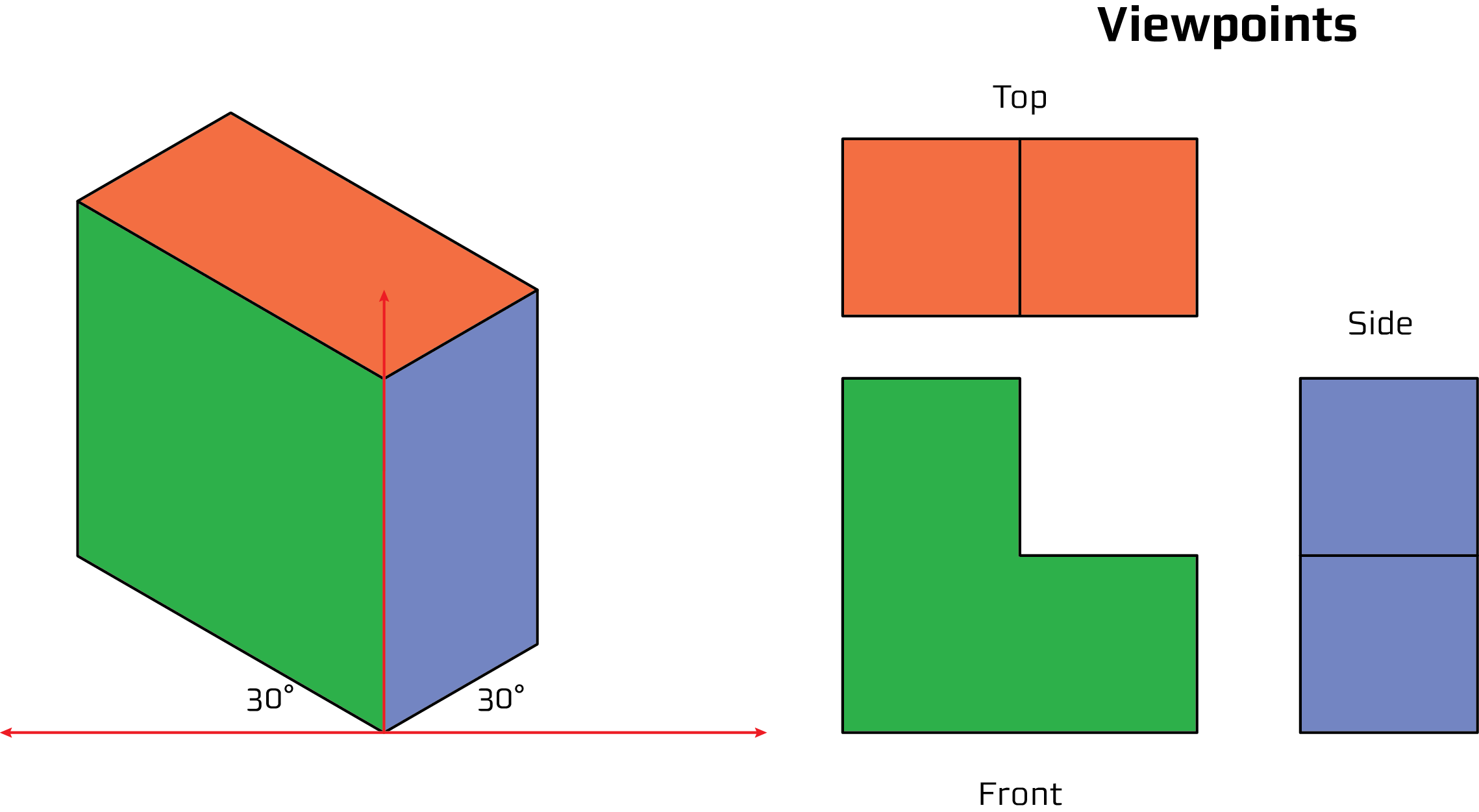
Front view
Right side view
Top view
'Nothing' view
The part of the projection that represents 'nothing' is the part you will have to machine block out.
Round projection
Most objects we make are not simply square or rectangular, they have circular shapes.
Remember the purpose of an isometic projection is to communicate shape, so the drawing does not need dimensions.
Watch the video to learn about isometric perspective for curved or round shapes.
Select image to view video.
Used with permission of Northern Alberta Institute of Technology.
Key points
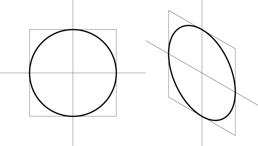
- A circle fits into a square
- Circle has to touch the square in four places
- True regardless of what angle the square is at
Holes and shafts
Remember: The drawing is based on rectangels of material we will machine down to make round objects.
Draw another small square in the middle to draw a hole.
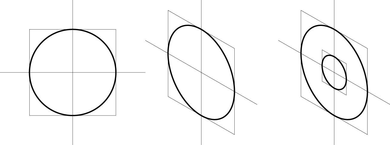
Add parallel lines to show the shaft - a hole that sticks out.

Cylinder
How to draw a cylinder
- Draw a circle on the front and then a matching one on the back.
- Draw lines to connect the two circles
- Erase the lines you do not need.

Shaft with hole
How to draw a shaft with a hole
- Draw your cylinder.
- Draw a smaller circle on the front in the same way you drew the other circles.

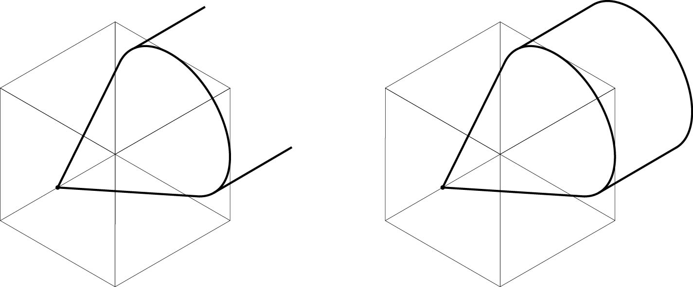
Tapered shaft
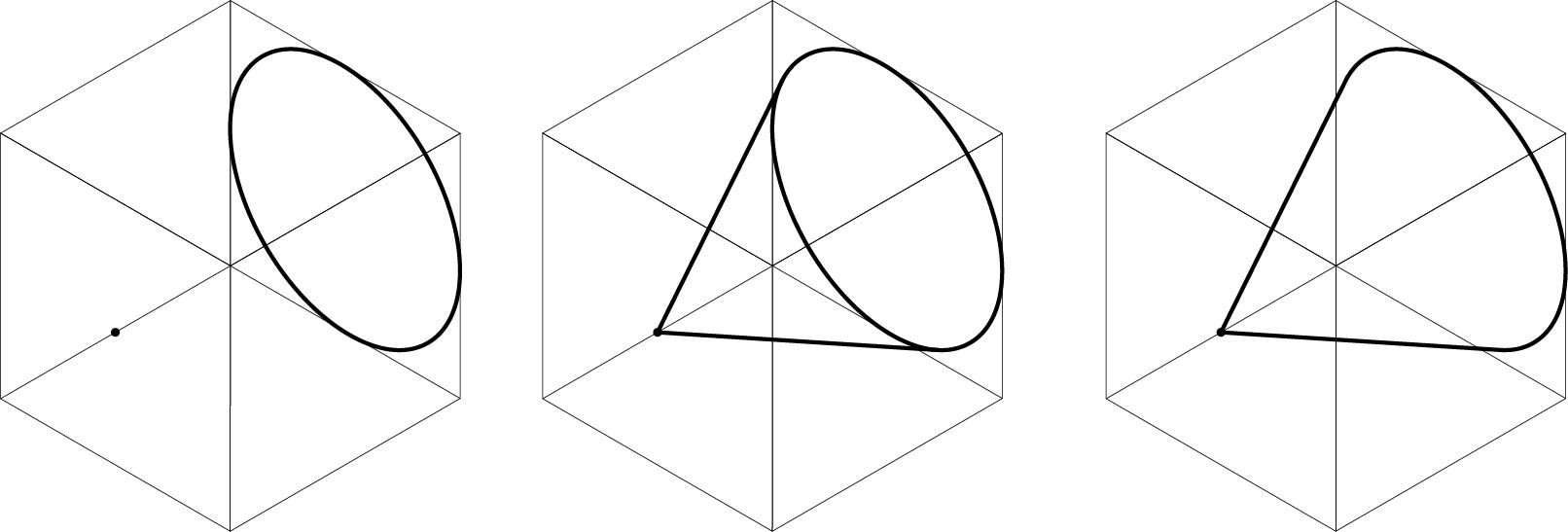
How to draw a tapered shaft
- Draw a box.
- Draw a cicle on the back and a dot (or smaller circle) in the middle at the front.
- Draw lines from 'dot' to circle.
- Erase lines you do not need.
5. Extend lines at the back.
6. Connect these with a line that is the same shape as the one it is parallel to.
