Worksheet 11B - Total Resistance Network Calcs - Harder - Solutions and Commentary
Introduction
These circuits are worked out using series-parallel circuit calculations. The maximum simplification is that there are no nested parallel circuits at each step.
In other words:
- Calculations like \( R_1 + (R_2 + R_3) \parallel (R_4 + R_5) \parallel (R_6 + R_7) \) are done in a single step.
- Calculations like \( R_1 + (R_2 + R_3) \parallel (R_4 + R_5 \parallel (R_6 + R_7)) \) are broken down into multiple steps, due to the nested parallel calculation.
These rules are followed throughout these solutions.
Question 1
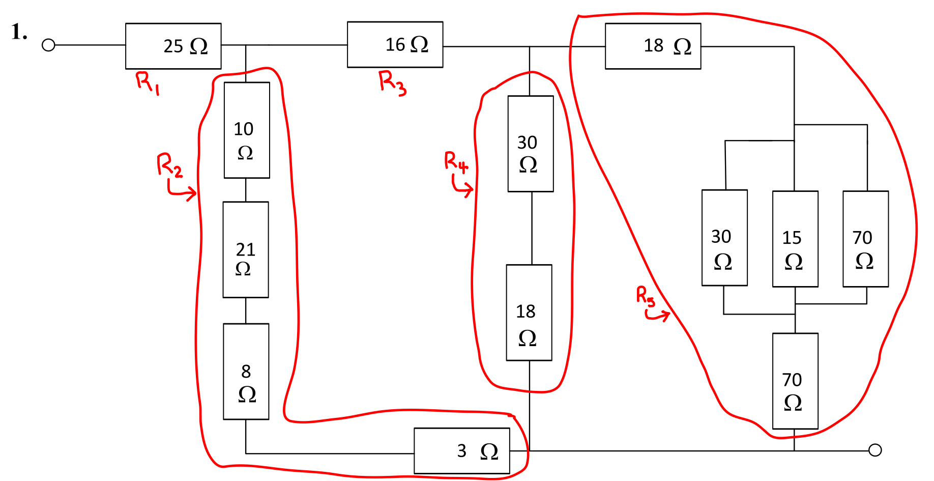
The circuit is shown below, with the resistors grouped into simple series-parallel sections.
Solution
The first step is to calculate the resistances as shown.
- \( R_1 = \) 25 Ω.
- \( R_2 = 10 + 21 + 8 + 3 = \) 42 Ω.
- \( R_3 = \) 16 Ω.
- \( R_4 = 30 + 18 = \) 48 Ω.
- \( R_5 = (18 + 70) + 30 \parallel 15 \parallel 70 = 88 + 8.75 = \) 96.75 Ω.
The circuit with these resistances calculated is shown below.
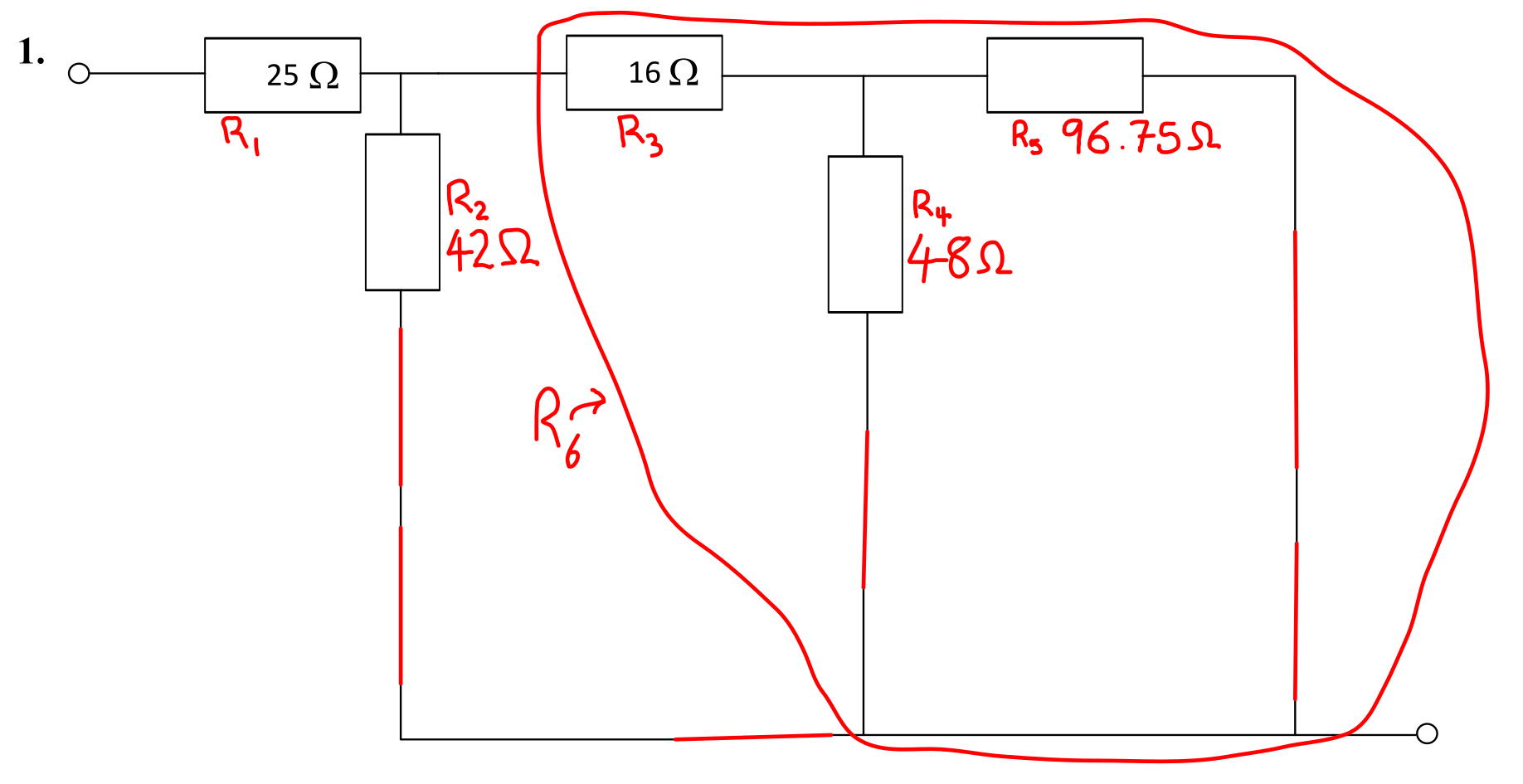
There is a new resistance, \( R_6 \), that requires calculation. The relevant resistances are shown below.
- \( R_1 = \) 25 Ω.
- \( R_2 = \) 33 Ω.
- \( R_3 = \) 16 Ω.
- \( R_6 = R_3 + R_4 \parallel R_5 = 16 + 48 \parallel 96.75 = 16 + 32.0829 = \) 48.0829 Ω (6 sf). The fractions at this point are too unwieldy, so all resistances will be handled numerically.
The circuit with these resistances calculated is shown below.
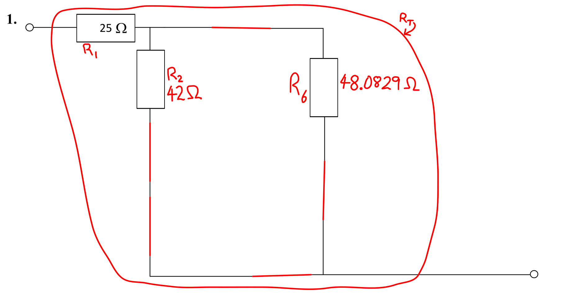
The total resistance, \( R_{\mathrm{T}} \), can now be calculated. The relevant resistances and calculations are shown below.
- \( R_1 = \) 25 Ω.
- \( R_2 = \) 33 Ω.
- \( R_6 = \) 48.0829 Ω.
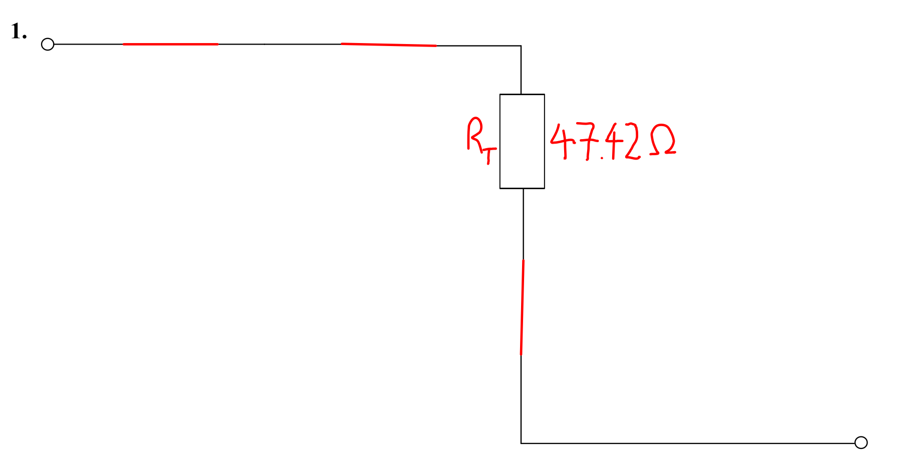
- \( R_{\mathrm{T}} = R_1 + R_2 \parallel R_6 = 25 + 42 \parallel 48.0829 = 25 + 22.4180 = \) 47.42 Ω (4 sf).
The final version of this circuit is shown below.
Question 2
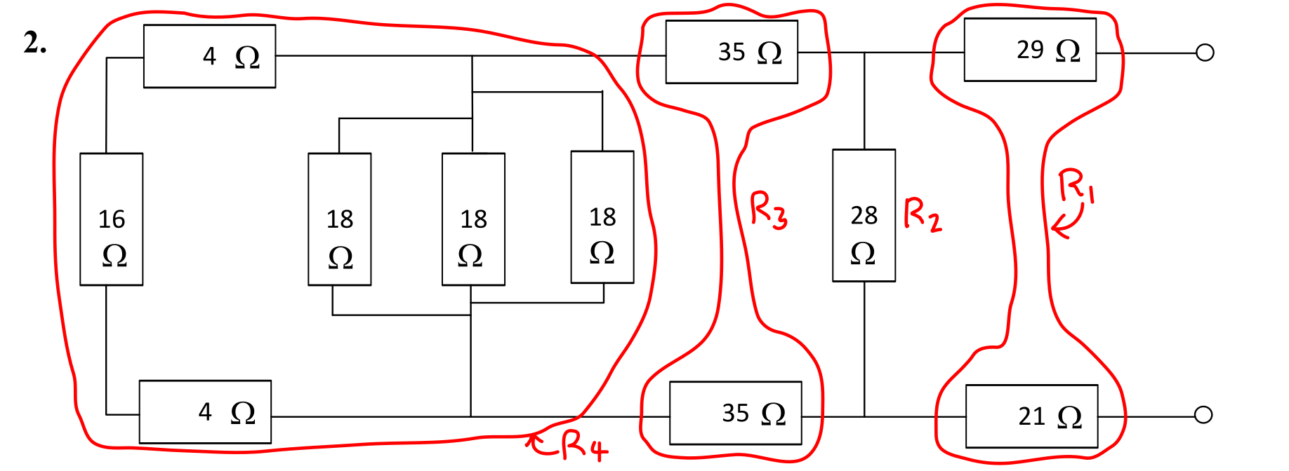
The circuit is shown below, with the resistors grouped into simple series-parallel sections.
Solution
The first step is to calculate the resistances as shown.
- \( R_1 = 21 + 29 = \) 50 Ω.
- \( R_2 = \) 28 Ω.
- \( R_3 = 35 + 35 = \) 70 Ω.
- \( R_4 = 18 \parallel 18 \parallel 18 \parallel (4 + 16 + 4) = 6 \parallel 24 = \) 4.8 Ω.
The circuit with these resistances calculated is shown below.

There is a new resistance, \( R_5 \), that requires calculation. The relevant resistances are shown below.
- \( R_1 = \) 21 Ω.
- \( R_2 = \) 56 Ω.
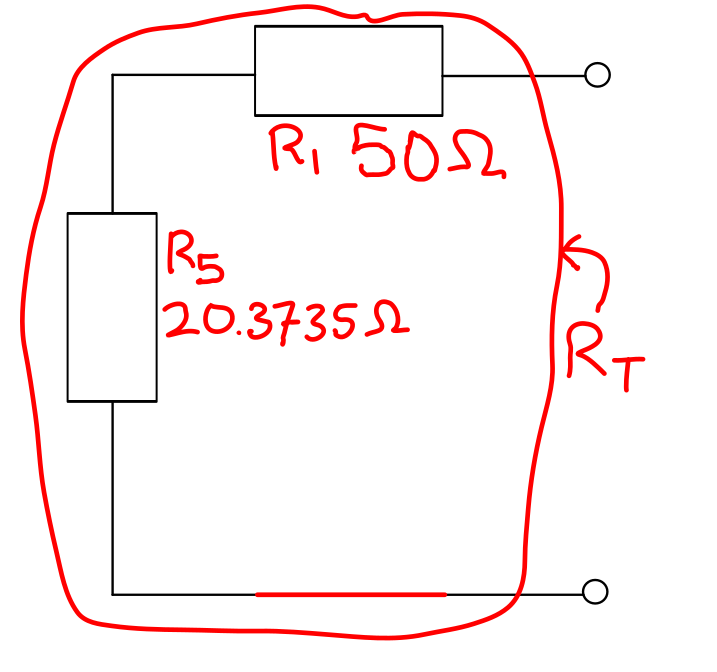
- \( R_5 = R_2 \parallel (R_3 + R_4) = 28 \parallel (70 + 4.8) = 28 \parallel 74.8 = \) 20.3735 Ω (6 sf).
The circuit with these resistances calculated is shown below.
The total resistance, \( R_{\mathrm{T}} \), can now be calculated. The relevant resistances and calculations are shown below.
- \( R_1 = \) 50 Ω.
- \( R_5 = \) 20.3735 Ω.
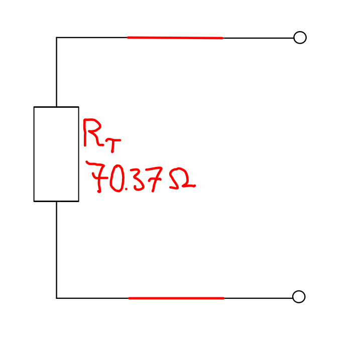
- \( R_{\mathrm{T}} = R_1 + R_5 = 50 + 20.3735 = \) 70.37 Ω (4 sf).
The final version of this circuit is shown below.
Question 3
The circuit is shown below, with the resistors grouped into simple series-parallel sections.

Solution
The first step is to calculate the resistances as shown.
- \( R_1 = \) 12 Ω.
- \( R_2 = \) 17 Ω.
- \( R_3 = \) 19 Ω.
- \( R_4 = \) 35 Ω.
- \( R_5 = 12 + 12 = \) 24 Ω.
- \( R_6 = \) 28 Ω.
- \( R_7 = 30 + 33 \parallel (28 + 45 + 15) = 30 + 33 \parallel 88 = 30 + 24 = \) 54 Ω.
The circuit with these resistances calculated is shown below.

There is a new resistance, \( R_8 \), that requires calculation. The relevant resistances are shown below.
- \( R_1 = \) 17 Ω.
- \( R_2 = \) 26 Ω.
- \( R_3 = \) 35 Ω.
- \( R_4 = \) 12 Ω.
- \( R_5 = \) 28 Ω.
- \( R_6 = \) 50 Ω.
- \( R_7 = \) 24 Ω.
- \( R_8 = R_5 + R_6 \parallel R_7 = 24 + 28 \parallel 54 = 24 + \frac{756}{41} = \) 42.4390 Ω (6 sf).
The circuit with these resistances calculated is shown below.
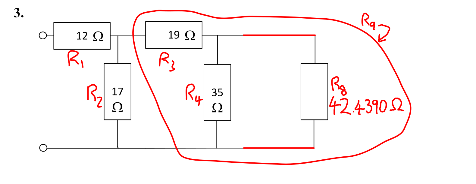
There is a new resistance, \( R_9 \), that requires calculation. The relevant resistances are shown below.
- \( R_1 = \) 17 Ω.
- \( R_2 = \) 26 Ω.
- \( R_3 = \) 35 Ω.
- \( R_4 = \) 12 Ω.
- \( R_8 = \) 42.4390 Ω.
- \( R_9 = R_3 + R_4 \parallel R_8 = 19 + 35 \parallel 42.4390 = 19 + 19.1811 = \) 38.1811 Ω.
The circuit with these resistances calculated is shown below.
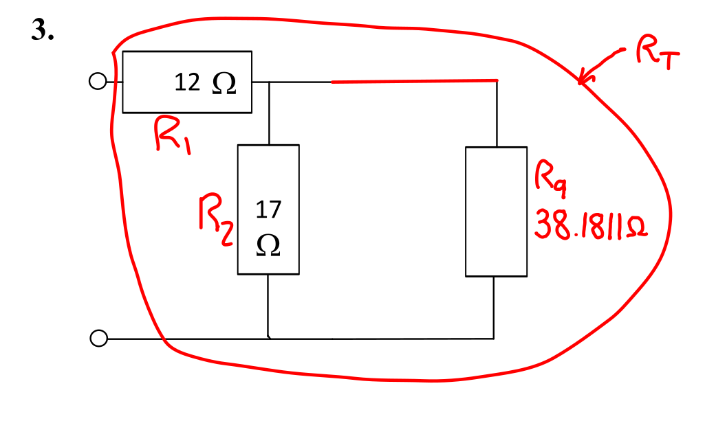
The total resistance, \( R_{\mathrm{T}} \), can now be calculated. The relevant resistances and calculations are shown below.
- \( R_1 = \) 17 Ω.
- \( R_2 = \) 26 Ω.
- \( R_9 = \) 38.1811 Ω.
- \( R_{\mathrm{T}} = R_1 + R_2 \parallel R_9 = 12 + 17 \parallel 38.1811 = 12 + 11.7627 = \) 23.76 Ω.
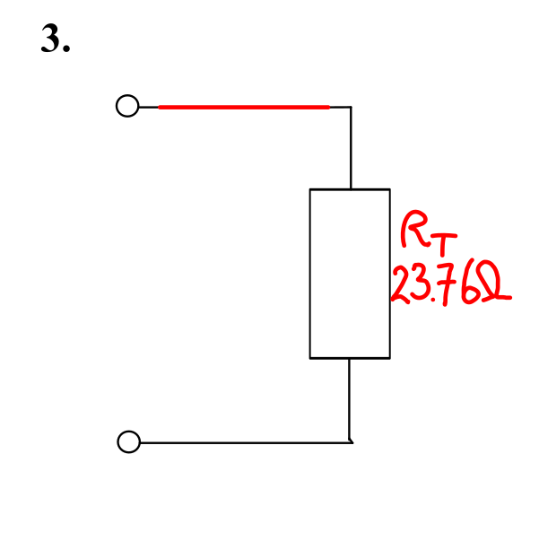
The final version of this circuit is shown below.
