Worksheet 15B - Basic Series-Parallel Calculations - Solutions and Commentary
Introduction
These circuits are worked out using series-parallel circuit calculations. The maximum simplification is that there are no nested parallel circuits at each step.
In other words:
- Calculations like \( R_1 + (R_2 + R_3) \parallel (R_4 + R_5) \parallel (R_6 + R_7) \) are done in a single step.
- Calculations like \( R_1 + (R_2 + R_3) \parallel (R_4 + R_5 \parallel (R_6 + R_7)) \) are broken down into multiple steps, due to the nested parallel calculation.
These rules are followed throughout these solutions.
Question 1
The marked up schematic is shown below.
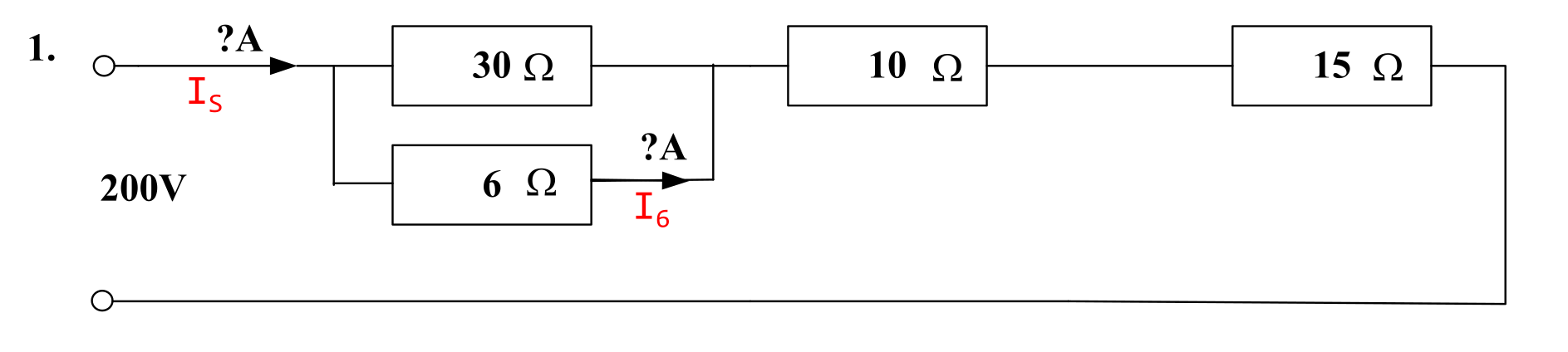
The objective is to calculate:
- the supply current \( I_{\mathrm{s}} \);
- the current through the 6 Ω resistor \( I_6 \).
Solution
The supply current is given by Ohm's Law
\( I_{\mathrm{s}} = \frac{V_{\mathrm{s}}}{R_{\mathrm{L}}} \)
where \( I_{\mathrm{s}} \) is the supply current, \( V_{\mathrm{s}} \) is the source/supply voltage, and \( R_{\mathrm{L}} \) is the total load resistance.
The load resistance is calculated using standard series-parallel workings.
\( R_{\mathrm{L}} = 30 \parallel 6 + 10 + 15 = 5 + 10 + 15 = \) 30 Ω.
The load current is now calculated by Ohm's Law.
\( I_{\mathrm{L}} = \frac{V_{\mathrm{s}}}{R_{\mathrm{L}}} = \frac{200}{30} = \) 6.66667 A (6 sf) or 6.667 A (4 sf) #.
The current through the 6 Ω resistor is evaluated by current division.
\( I_6 = I_{\mathrm{L}} \cdot \frac{30 \parallel 6}{6} = 6.66667 \cdot \frac{5}{6} = \) 5.556 A (4 sf) #.
Question 2
The marked up schematic is shown below.
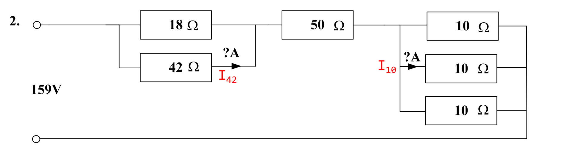
The objective is to calculate:
- the current through the 42 Ω \( I_{42} \);
- the current through the 6 Ω resistor \( I_6 \).
Solution
The load current is given by Ohm's Law.
\( I_{\mathrm{L}} = \frac{V_{\mathrm{s}}}{R_{\mathrm{L}}} \)
where \( I_{\mathrm{L}} \) is the load current, \( V_{\mathrm{s}} \) is the source/supply voltage, and \( R_{\mathrm{L}} \) is the total load resistance.
The load resistance is calculated using standard series-parallel workings.
\( R_{\mathrm{L}} = 18 \parallel 42 + 50 + 10 \parallel 10 \parallel 10 = 12.6 + 50 + 3.33333 = \) 65.9333 Ω.
The load current is now calculated by Ohm's Law.
\( I_{\mathrm{L}} = \frac{V_{\mathrm{s}}}{R_{\mathrm{L}}} = \frac{159}{65.9333} = \) 2.41153 A # (6 sf).
The current through the 42 Ω resistor is evaluated by current division.
\( I_{42} = I_{\mathrm{L}} \cdot \frac{18 \parallel 42}{42} = 2.41153 \cdot \frac{12.6}{42} = 2.41153 \cdot 0.3 = \) 0.7235 A (4 sf) #.
The current through the 10 Ω resistor is evaluated by current division.
\( I_{10} = I_{\mathrm{L}} \cdot \frac{10 \parallel 10 \parallel 10}{10} = 2.41153 \cdot \frac{\left ( \frac{10}{3} \right )}{10} = 2.41153 \cdot \frac{1}{3} = \) 0.8038 A (4 sf) #.
Question 3
The marked up schematic is shown below.
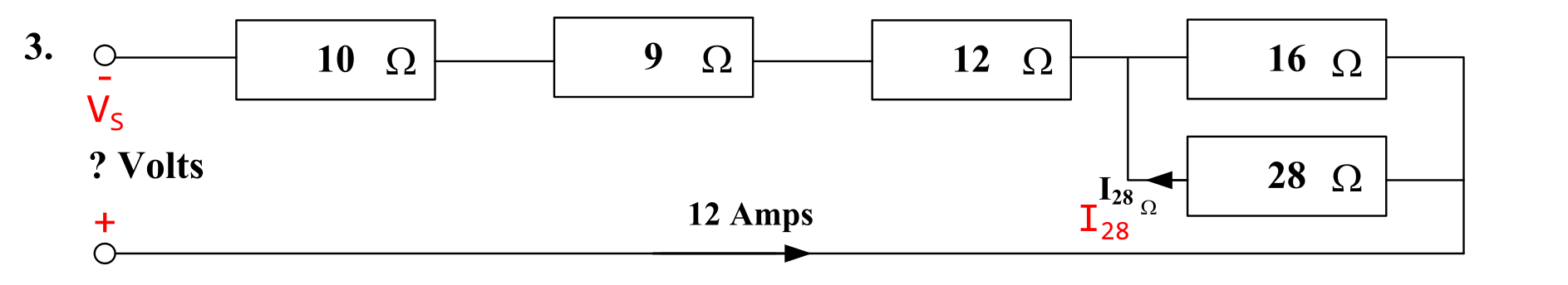
The objective is to calculate:
- the supply voltage \( V_{\mathrm{s}} \);
- the current through the 28 Ω resistor \( I_{28} \).
Solution
The supply voltage is given by Ohm's Law.
\( V_{\mathrm{s}} = I_{\mathrm{L}} R_{\mathrm{L}} \)
where \( V_{\mathrm{s}} \) is the source/supply voltage, \( I_{\mathrm{L}} \) is the load current, and \( R_{\mathrm{L}} \) is the total load resistance.
The load resistance is calculated using standard series-parallel workings.
\( R_{\mathrm{L}} = 10 + 9 + 12 + 16 \parallel 28 = 31 + 10.1818 = \) 41.1818 Ω.
The supply voltage is now calculated by Ohm's Law.
\( V_{\mathrm{s}} = I_{\mathrm{L}} R_{\mathrm{L}} = 12 \cdot 41.1818 = \) 494.182 V (6 sf) or 494.2 V (4 sf) #.
The current through the 28 Ω resistor is evaluated by current division.
\( I_{10} = I_{\mathrm{L}} \cdot \frac{16 \parallel 28}{28} = 12 \cdot \frac{10.1818}{28} = 12 \cdot 0.363636 = \) 4.364 A (4 sf) #.
Question 4
The marked up schematic is shown below.
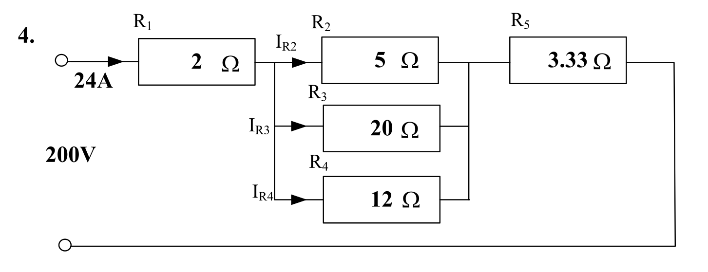
The objective is to calculate:
- the current through \( R_2 \): \( I_{R2} \);
- the current through \( R_3 \): \( I_{R3} \);
- the current through \( R_4 \): \( I_{R4} \).
NOTES:
- This circuit as shown is inconsistent. It is not possible to have the combination of supply voltage, load current and resistances shown. This is because \( R_5 \) should be \( \frac{10}{3} \) Ω, not 3.33 Ω. The effects of this will be discussed in the solutions.
- This circuit is identical to the circuit in Worksheet 15A, Q4, except the voltage source value is doubled. Because the circuit has linear components, all of the voltages and currents will be exactly double the voltages and currents in Worksheet 15A Q5.
Solution - Current Division
The unknowns may be computed by means of current division.
The formula for current division is
\( I_{Rn} = I_{\mathrm{T}} \cdot \frac{R_{\mathrm{T}}}{R_n} \)
where \( I_{Rn} \) is the current through resistor \( R_n \), \( I_{\mathrm{T}} \) is the total current through all the parallel resistors, and \( R_{\mathrm{T}} \) is the total parallel resistance of all the parallel resistors.
The total resistance is calculated using the standard parallel resistance workings.
\( R_{\mathrm{T}} = 5 \parallel 20 \parallel 12 = \) 3 Ω.
The currents through the individual resistances can now be calculated using the current division formula. Note that the total current is 12 A.
\( I_{R2} = 24 \cdot \frac{3}{5} = \) 14.4 A #.
\( I_{R3} = 24 \cdot \frac{3}{20} = \) 3.6 A #.
\( I_{R4} = 24 \cdot \frac{3}{12} = \) 6 A #.
The total current is 24 A, which matches the total given.
Solution - Ohm's Law
The unknowns may be computed by means of Ohm's Law.
The currents through \( R_2 \) through \( R_4 \) may be found using the voltage drop across these resistors. This voltage drop will be called \( V_{R2} \).
\( V_{R2} = V_{\mathrm{s}} - V_{R1} - V_{R5} = 200 - 24 \cdot (2 + 3.33) = 200 - 127.92 = \) 72.08 V (4 sf).
The currents through the individual resistances can now be calculated using Ohm's Law.
\( I_{R2} = \frac{72.08}{5} = \) 14.42 A # (4 sf).
\( I_{R3} = \frac{72.08}{20} = \) 3.604 A # (4 sf).
\( I_{R4} = \frac{72.08}{12} = \) 6.006 A # (4 sf).
NOTE: The currents do not quite "balance". This is because the 3.33 Ω resistor is not specified precisely enough to produce 24 A load current to 4 sf. In this case, the method using current division is more precise, as it uses the 24 A load current directly. It does not use the imprecise 3.33 Ω resistor.
Question 5
The marked up schematic is shown below.
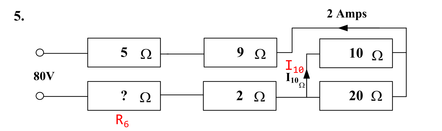
The objective is to calculate:
- the unknown resistance \( R_6 \);
- the current through the 10 Ω resistor \( I_{10} \).
Solution
While \( R_6 \) is not known, the total resistance \( R_{\mathrm{T}} \) can be calculated from the supply voltage and current.
\( R_{\mathrm{T}} = \frac{V_{\mathrm{s}}}{R_{\mathrm{L}}} = \frac{80}{2} = \) 40 Ω.
The total resistance is 40 Ω. The unknown resistance \( R_6 \) is calculated by subtracting the known resistances from the total.
\( R_6 = R_{\mathrm{T}} - 5 - 9 - 10 \parallel 20 - 2 = 40 - 16 - 6.66667 = \) 17.3333 Ω (6 sf) or 17.33 Ω (4 sf) #.
The current through the 10 Ω resistor is evaluated by current division.
\( I_{10} = I_{\mathrm{L}} \cdot \frac{10 \parallel 20}{10} = 2 \cdot \frac{6.66667}{10} = 2 \cdot 0.666667 = \) 1.333 A (4 sf) #.