Electromagnetism Resource
4. Electromagnetic Effects
4.5. Electromagnetic Induction in Motors and Generators (Fleming's Rules)
Any conductor that is moved in a magnetic field will generate an electromotive force (EMF). This EMF can be sued to generate currents, voltages and torques.
The Lorentz Force
The basic effect governing the effect on moving conductors in magnetic fields is called the Lorentz Force.
The Lorentz Force governs the relationship between the electric field, magnetic flux density, and conductor velocity.
The Lorentz Force is used to derive the electromotive force generated when a wire is moved in a magnetic field. This effect is used in motors and generators to generate voltage, current and torque.
The Lorentz Force equation is given below:
\( E = B v \sin \theta \)
where \( E \) is the magnitude of the electric field, (V.m-1), v is the magnitude of the velocity (m.s-1), and \( \theta \) is the angle between the velocity and the magnetic field.
The direction of the electric field is determined using the right-hand rule as shown below.
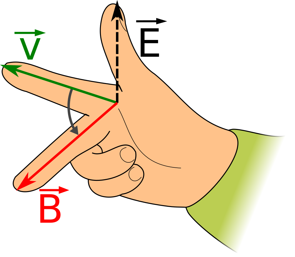
Normally, the value of the electric field is not usually as important as the total voltage, or electromotive force.
The electromotive force is dependent on:
- the electric field; and
- the total length of winding conductor that is parallel to the electric field a.k.a the effective conductor length.
The equation for electromotive force of a moving winding is given below:
\( \mathcal{E} = B l v \sin \theta \)
where \( \mathcal{E} \) is the electromotive force, (V), \( l \) is the effective conductor length (m), v is the magnitude of the velocity of the winding (m.s-1), and \( \theta \) is the angle between the velocity and the magnetic field.
The quantity \( v \sin \theta \) is the component of the velocity at right angles to the magnetic field. This is sometimes referred to as the coil "cutting" magnetic field lines. The faster the coil cuts magnetic field lines, the higher the EMF.
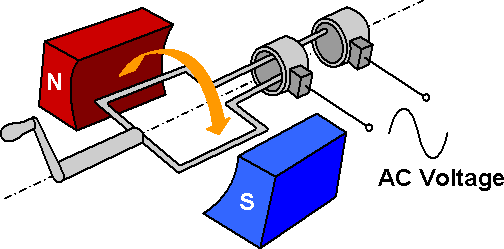
The picture below shows a simple alternator, which is used to generate a voltage by moving a winding in a magnetic field provided by the permanent magnets.
Fleming's Rules
Fleming's Rules are used to determine the direction of the current in a motor or generator winding.
There are two versions: Fleming's Left Hand Rule for Motors, and Fleming's Right Hand Rule for Generators.
The rules are different because the relationship between current and EMF is different for motors and generators.
A motor (or generator) that is rotating in a given direction, with a given magnetic field will always produce the same EMF.
The difference is the following:
- in a generator, the current flow is in the same direction as the the electric field (current is parallel to the electric field); and
- in a motor, the current flow is in the opposite direction to the the electric field (current is anti-parallel to the electric field).
In the right-hand rule for the Lorentz Force, the output (electric field) is on the thumb. In Fleming's Rules, the output (winding current) is on the middle finger.
A version of the Lorentz Force using the middle finger as output is shown below.
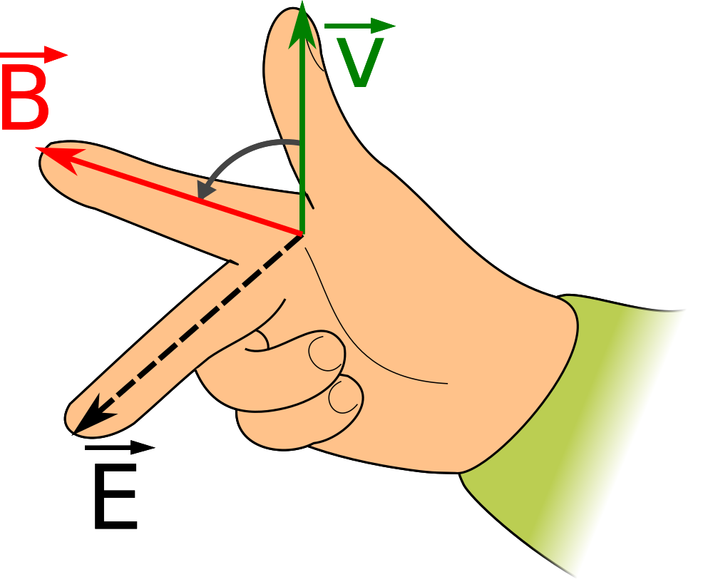
This diagram forms the basis for Fleming's Rules.
Fleming's Right-Hand Rule for Generators
Flemings Right-Hand Rule for Generators is derived from the Lorentz Force in the following way:
- replacing velocity with force (i.e. the force maintaining that velocity in a generator);
- replacing electric field with electric current flowing in the same direction.
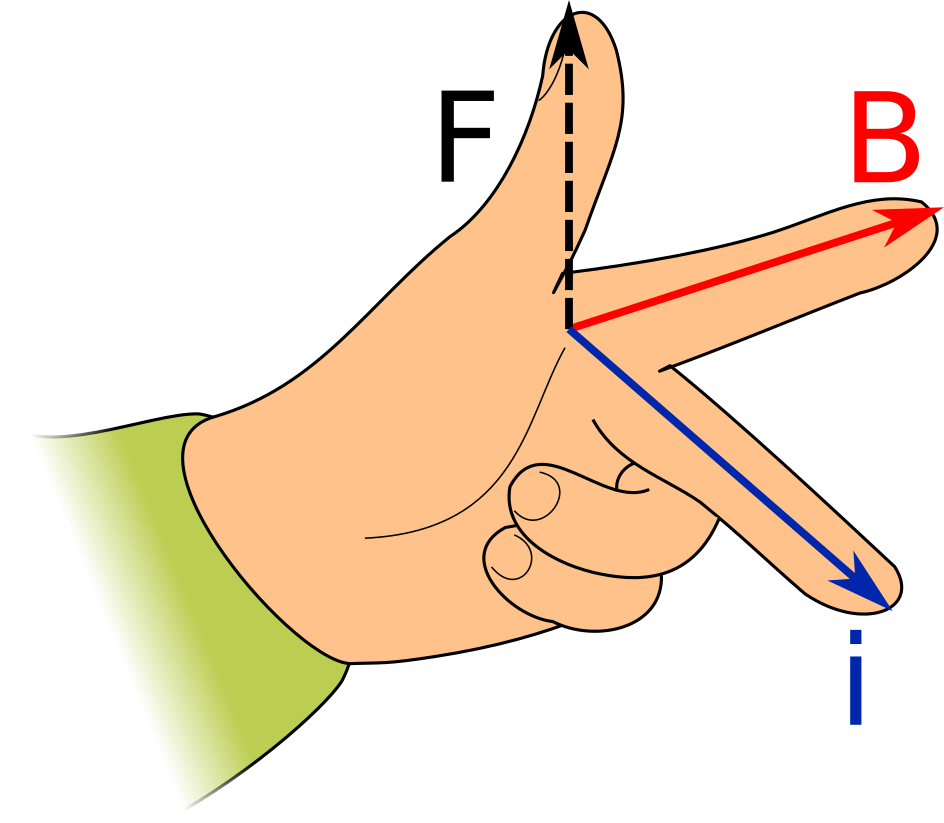
Doing these steps produces Fleming's Right-Hand Rule for Generators as pictured below.
\( F \) represents the force exerted on the winding (i.e. the force that makes the winding move), \( B \) represents the magnetic field. and \( i \) represents the direction of induced current flow.
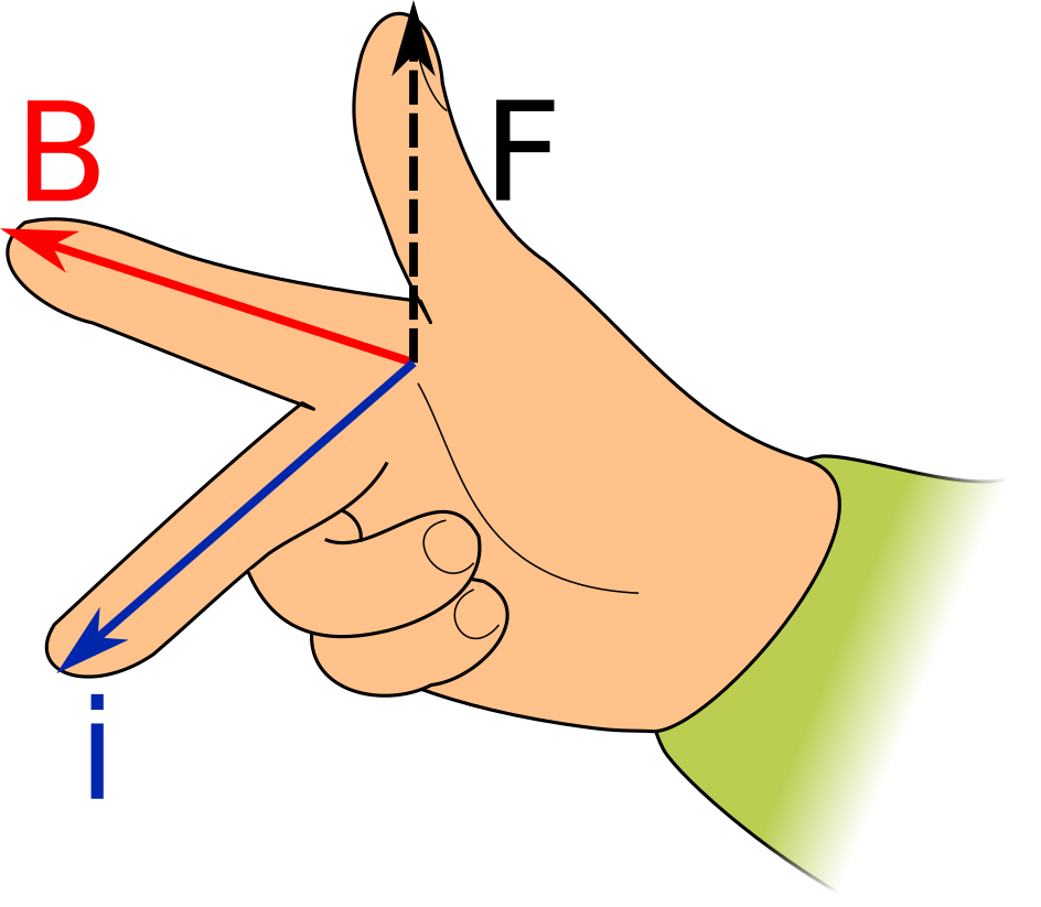
Fleming's Left-Hand Rule for Motors
Flemings Right-Hand Rule for Motors is derived from the Lorentz Force in the following way:
- replacing velocity with force (i.e. the force maintaining that velocity in a generator);
- replacing electric field with electric current flowing in the opposite direction.
Reversing the direction results in a right-hand rule where the current is going in the exact opposite direction to the right middle finger. Luckily, since the left hand is a mirror image of the right hand, the current can be aligned along the middle finger by using the left hand to "mirror" the middle finger.
Doing these steps produces Fleming's Left-Hand Rule for Motors as pictured below.
