Electromagnetism Resource
3. Electric and Magnetic Fields
3.6. Temporary (Soft) Magnets
Temporary magnets are usually made of "soft" magnetic materials, in the sense that:
- soft magnetic materials lose their magnetic field after an external field is removed; and
- soft magnetic materials are easy to magnetise and de-magnetise using an external magnetic field.
Any substance (including free space with \( \mu_{\mathrm{r}} = 1\)) is technically a soft magnet, but the term usually refers to magnetic materials (high permeability) that can have their magnetisation easily changed. Common examples of soft magnetic materials include transformer steel, silicon steel and soft iron.
Soft magnetic materials are useful in:
- transformers, because soft magnetic materials produce lower losses;
- iron filings used to see magnetic fields; and
- lifting magnets, bells, contactors, relays, solenoids, and locking magnets, where the holding force needs to disappear when the current is turned off.
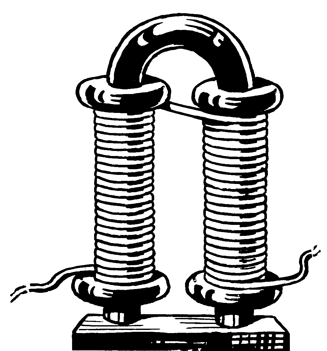
Electromagnets
A coil of wire can be used to generate a controllable magnetic field by varying the current flow in the coil. This type of magnet is called an electromagnet, solenoid or coil. A solenoid with a U-shaped core is shown below.
Magnetising Force
The magnetising force \( H \) is given by the equation:
\( H = \frac{N I}{l} \)
where \( H \) is the magnetising force (A.m-1), \( I \) is the magnetising current (A), \( l \) is the total effective length of the magnetic circuit (m), and \( N \) is the number of turns.
In the case of the electromagnet above, the magnetic circuit length is the length all the way from the end of one coil, through the pole piece, through the end of the other coil, and back to the end of the first coil.
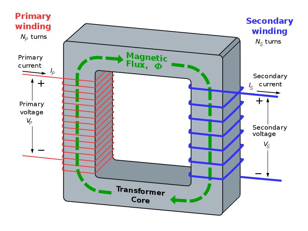
Transformers
Another common electromagnet is the transformer. The magnetic circuit is through the transformer core, which for efficiency has a permeability as high as possible.
The primary winding is used to generate a magnetising force that ends up generating an EMF in the secondary winding.
B-H Curves
The most important curve when designing electromagnets is the B-H curve. A set of B-H curves are shown below for various types of steels. Note the levelling off of the curve of B-H at about 1-2 T. This is the effect of magnetic saturation.
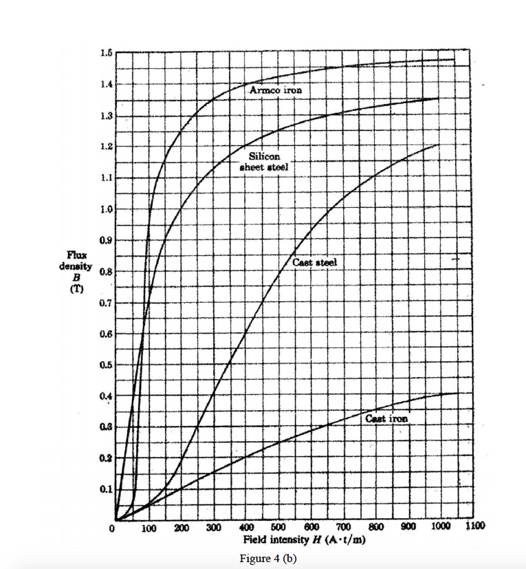
The curves are determined experimentally for each material. The slope of the curve is the value of \( \mu \) at that particular magnetising field strength.
The "average" permeability is given by \( \frac{B}{H} \). The "average" relative permeability is given by \( \frac{B}{\mu_0 H} \).
The horizontal axis is in "amp-turns per metre". The meaning of this is that if you need 500 amp-turns, you could get that magnetising force in any one of the following ways:
- 1 turn of wire carrying 500 A;
- 5 turns of wire carrying 100 A;
- 100 turns of wire carrying 5 A;
- 500 turns of wire carrying 1 A;
- or any other combination of turns and current such that the product \( N I \) is 500.
Electromagnet Forces
Electromagnets are capable of producing a physical force on magnetisable materials. The force is given by:
\( F = \frac{B^2 A}{2 \mu_0} \)
where \( F \) is the force (N), \( B \) is the magnetic field (T), \( A \) is the area of the magnetic circuit (m2), and \( \mu_0 \) is the magnetic permeability of free space (H.m-1).
The value of \( B \) at a particular value of \( H \) is obtained by reading a B-H curve like the one above.