Electromagnetism Resource
5. Applications and Examples
5.1. Relays and Contactors
Relays and contactors are switches that are activated by electromagnets. They enable a small signal to switch a much larger signal. Relays are generally smaller than contactors and often have two position contacts.
A labelled image of a relay is shown below.
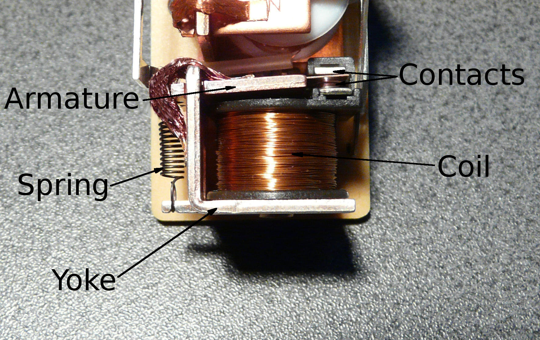
Relays consist of a coil wound on a yoke, and an armature that is moved when a current flows in the relay coil. The movement moves the armature between one or more sets of contacts. When the current stops, the spring on the left pulls the armature to its unenergised position.
No electrical contact is required between the circuit that drives the coil and the switched output. Relays are therefore useful because they provide electrical isolation between the coil and the switched output.
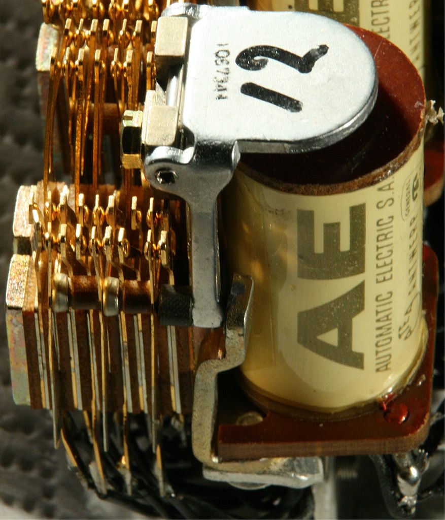
Another example of a relay is shown below. In the relay below, the armature (labelled 12) is pulled down when enough current flows in the coil. The armature is connected mechanically to a spring-loaded contact arm. The movement of the armature will move the contact arm from being in contact with one set of contacts to another. In this way, a relay can be used to switch its outputs. When the current is stopped, the force on the armature stops, and the spring pulls the contact back to its 'off' position.
Contactors
A contactor is similar to a relay except that contactors are designed for higher power circuits. They also have single action contacts that are only designed to switch a load when current is present in the coil. A contactor is shown below.
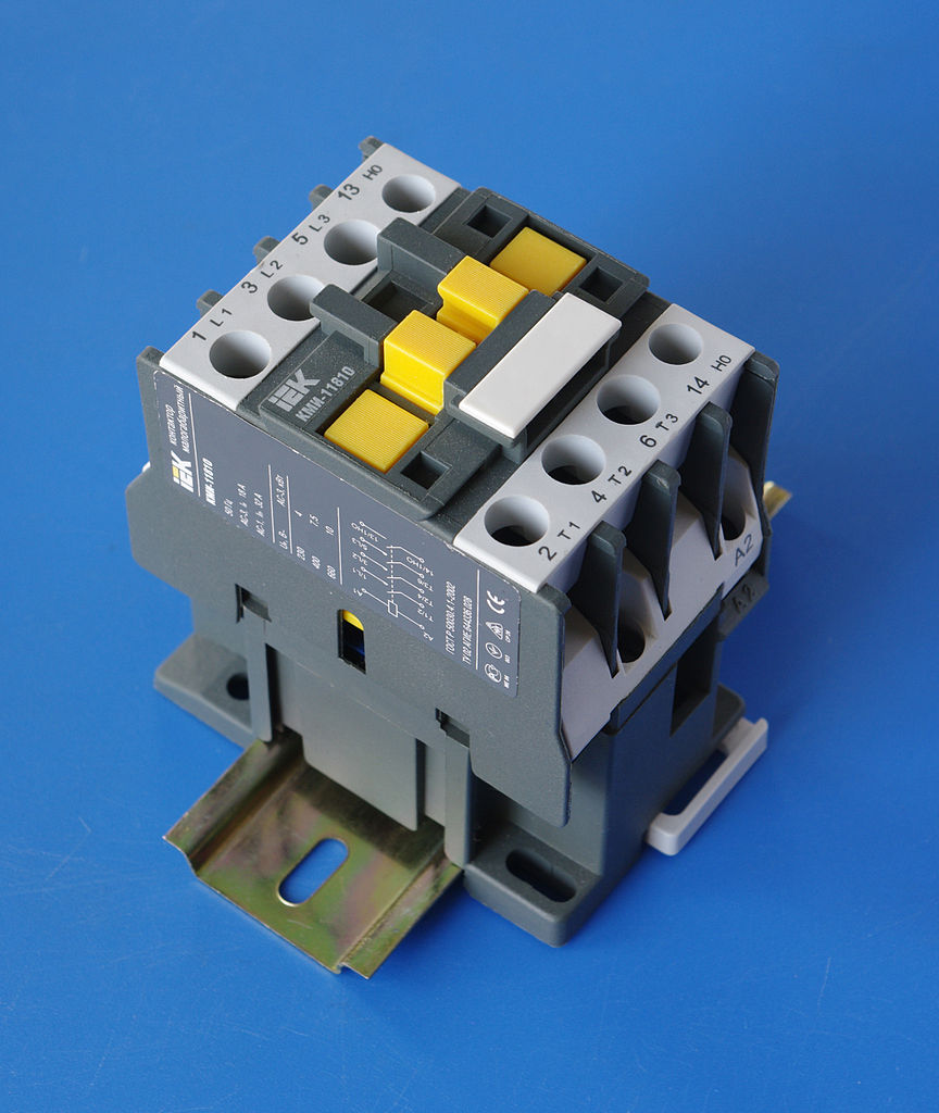
Contactors are designed with auxiliary contacts to signal when the contactor is on or off, and extra devices (e.g. delay timers) can be attached to the armature at top of the contactor (the yellow part).
Relay Contact Configurations
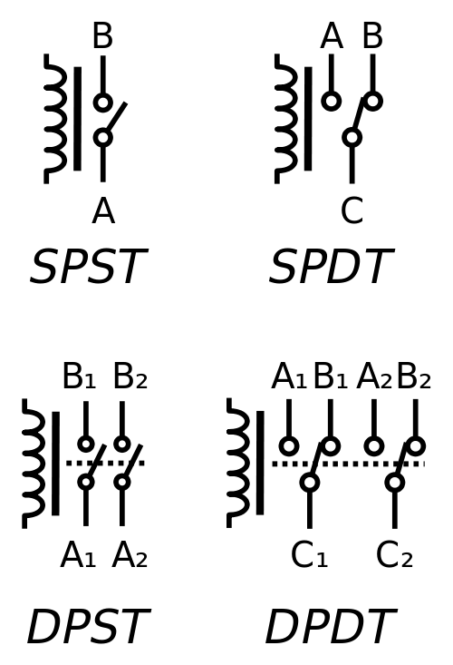
Relays are highly flexible in how their contacts are arranged. Some example arrangements are shown below.
The symbol on the left is the coil. The coil is energised by a control circuit.
An explanation of the contacts follows.
The terminals in the relays above are given letter identifiers. The table below explains how the contacts change.
Poles and Throws
The relays above are defined by poles and throws.
A pole is a set of contacts, denoted by 'P'. SP means 'single pole' (single set of contacts), and DP means 'double pole' (double set of contacts). There is no upper limit on the number of poles. Some relays used in telephone exchanges use 30 poles or more.
A throw is a contact. A single throw pole has a single contact, that is either connected or disconnected when the relay is energised. A double throw pole has two contacts. When the relay is de-energised, the common terminal is connected to one of the throw contacts. When the relay is energised, the common terminal is connected to the other contact.