Electromagnetism Resource
5. Applications and Examples
5.2. Transformers
A transformer uses magnetic fields to transfer energy from one circuit to another.
There are two main types of transformers:
- Isolating transformers, where there are at least two coils. The coils do not need to be electrically connected together. Isolating transformers can have any number of coils.
- Autotransformers, which have one coil only. The output is a connection, or "tap" off the same coil. Autotransformers do not provide electrical isolation between input and output.
Although transformers could theoretically operate off DC, in practice this is not possible because DC would require an unlimited amount of magnetic flux. Therefore, transformers are purely AC devices.
Transformers have a primary winding, and in the case of isolating transformers, one or more secondary windings. Power is transferred from the primary winding to the secondary windings.
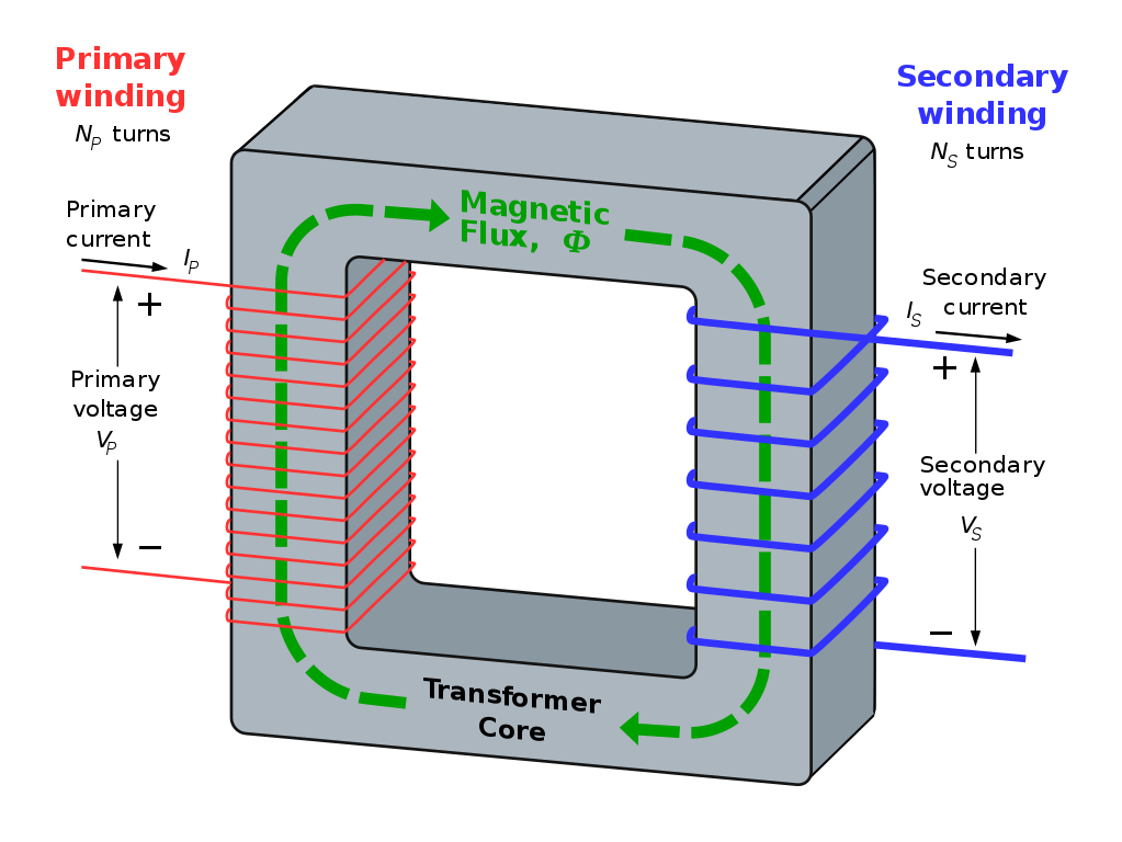
The illustration below shows a two-winding transformer. As previously discussed, the two winding are called the primary and secondary windings. The primary winding has \( N_P \) turns, and the secondary winding has \( N_S \) turns.
For an ideal transformer, the following rules hold. A real transformer will not obey these rules, but should be close.
- \( I_P = 0 \) when \( I_S = 0 \) i.e. there is no magnetising current. A real transformer has some magnetising current flowing in the primary at all times.
- \( V_S I_S = V_P I_P \) i.e. no power losses. In a real transformer, \( V_S I_S < V_P I_P \) due to wire and core losses.
- \( V_S = \frac{N_S}{N_P} V_P \) i.e. the secondary voltage is determined only by the turns ratio. In a real transformer, the voltage will be less than this, or extra turns will be added to the secondary to raise the voltage at rated current.
- \( I_S = \frac{N_P}{N_S} I_P \) i.e. the secondary current is determined only by the turns ratio. In a real transformer, the current will be less than this, or extra turns will be added to the primary to raise the current at rated current.
- The primary flux is directly proportional to the primary voltage divided by the primary voltage's frequency and number of turns i.e. \( \Phi \propto \frac{V_P}{N_P f} \), where f is the frequency of the AC supply in hertz.
- The core never saturates.
- All the primary flux links to the secondary (there is no "leakage flux". In practice, there is some leakage flux.
- There is no lower limit on the number of primary turns. In practice, a minimum number of primary turns is required to keep the magnetising current low, and to keep the core from saturating.
- There are no losses from winding resistance. In practice, this must be compensated for in the design.
- There are no core losses. In practice, this must be compensated for in the design, such as by using laminated cores to reduce eddy current losses in the core.
The secondary voltage \( V_S \) is generated by the secondary coils being subject to a changing magnetic field generated by the primary. The changing magnetic field provides the "movement" required to generate an EMF in the secondary coil. In other words, \( V_S = -\mathcal{E} = N_S \frac{\Delta \Phi}{\Delta t} \).
Although the secondary voltage is predicted as being negative, the primary and secondary coils are wound in the opposite directions to each other, so the secondary coil voltage has the same polarity as the primary voltage at all times.