Electromagnetism Resource
5. Applications and Examples
5.4. AC Generator (Alternator)
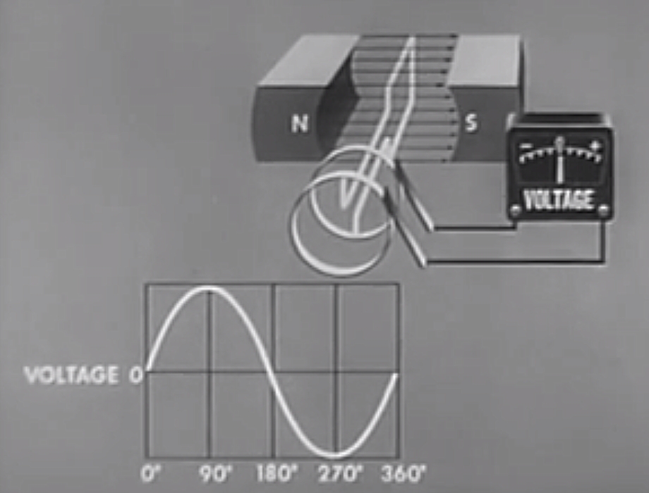
We now turn our attention to an actual example if an AC generator, or alternator. There are a series of five pictures of a single loop alternator at 0°, 90°, 180°, 270° and 360° of rotation. The single loop coil is being turned clockwise.
The path for calculating \( \mathcal{E} \) goes from the front slip ring to the rear slip ring. The parts of the coil that generate an EMF at all the the two parts that are at 90° to the magnetic field lines. The rear part of the coil does not generate any EMF at all, any electric field is always at 90° to the wire.
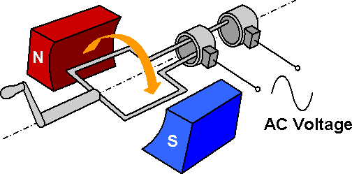
The simplest form of an AC generator is shown below. The simplest example consists of a single loop of wire, a magnet, slip rings and a load, as shown below.
The basic equation for the voltage from an AC generator is:
\( \mathcal{E}(t) = B l v \sin (\omega t) \)
where \( \mathcal{E}(t) \) is the instantaneous electromotive force (V), \( B \) is the magnetic flux density from the magnet (T), \( l \) is the total length of the wire at 90° to the magnetic field (m), \( v \) is the circular velocity of the coil (m.s-1), \( \omega \) is the angular velocity of the coil (rad.s-1), and \( t \) is time (s). The length \( l \) depends on the number of turns of the generating coil, adding more turns increases the length.
The magnitude of the circular velocity is given by \( v = r \omega \), where \( r \) is the radius of the coil (m). Using \( r \omega \) for the circular velocity gives:
\( \mathcal{E}(t) = B l r \omega \sin (\omega t) \)
This formula shows that the output is proportional to the angular velocity.
Knowing this, these are some ways to increase the peak EMF from the generator:
- Increase \( B \): Use a stronger magnet.
- Increase \( \omega \): Turn the generator faster.
- Increase \( v \) by increasing \( \omega \): Turn the generator faster.
- Increase \( v \) by increasing \( r \): Make the radius of the coils larger.
- Increase \( l \): Make the generator longer.
- Increase \( l \): Put more turns on the generator coil.
Determining "Real-Time" EMF
Determining the behaviour of an alternator can be tricky. The following features of an alternator affect the polarity:
- the direction of rotation as viewed from the slip rings (clockwise or anticlockwise);
- the orientation of the magnetic poles relative to the rotation (N-S or S-N);
- whether the polarity is considered positive at the front slip ring or negative at the front slip ring;
- whether the path of the coil from the negative slip ring to the positive slip ring goes clockwise or anticlockwise relative to the magnetic field at zero degrees of rotation (the winding orientation of the coil).
Changing any one or three of these features will reverse the polarity. Changing two or four of them will not affect the polarity.
We now turn our attention to an actual example. There are a series of five pictures of a single loop alternator at 0°, 90°, 180°, 270° and 360° of rotation. The single loop coil is being turned clockwise.
The path for calculating \( \mathcal{E} \) goes from the front slip ring to the rear slip ring. The parts of the coil that generate an EMF at all the the two parts that are at 90° to the magnetic field lines. The rear part of the coil does not generate any EMF at all, any electric field is always at 90° to the wire.
In terms of the attributes above that affect the polarity, the example alternator has the following attributes.
- the direction of rotation is clockwise as viewed from the slip rings;
- the magnetic poles are oriented N-S;
- the front slip ring is considered the negative terminal, the rear slip ring is considered the positive terminal;
- the coil is wound clockwise relative to the magnetic field, as the correct winding orientation of the coil is found using the left hand, with the thumb pointing in the direction of the magnetic field.
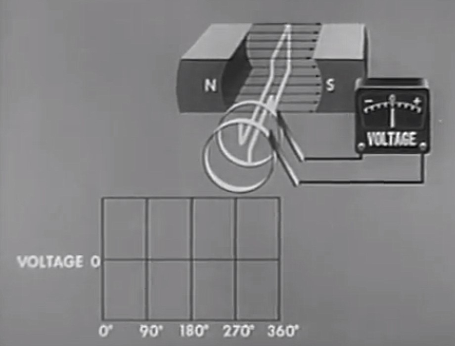
Zero Degrees (\( \theta = 0^{\circ} \))
At zero degrees, the armature is moving to the right (top wire) and left (bottom wire). But the wire is moving parallel to the magnetic field. So \( \theta = 0^{\circ} \), and the EMF is therefore zero too.
90 Degrees (\( \theta = 90^{\circ}\))
At 90 degrees of rotation, the coils are moving at their maximum speed relative to the magnetic field. It can also be said they are "cutting" the maximum number of magnetic field lines.
The EMF is therefore at a maximum, since \( \theta = 90^{\circ} \).
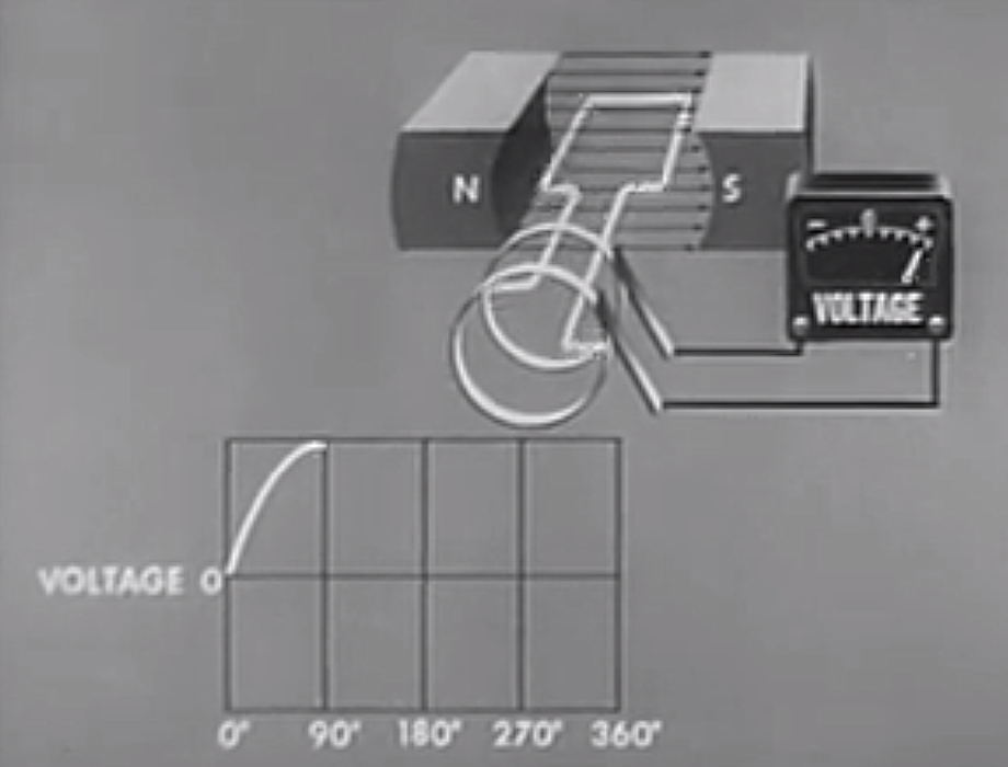
The relative orientations of the magnetic field and velocity will tell us whether the EMF is positive or negative at that instant.
On the right, the velocity is straight down, and the magnetic field is from left to right. Therefore, by \( \vec{E} = \vec{v} \times \vec{B} \), the electric field must be oriented towards the slip rings.
On the left, the velocity is straight up, and the magnetic field is from left to right. Therefore, by \( \vec{E} = \vec{v} \times \vec{B} \), the electric field must be oriented away from the slip rings.
However, because of the orientation of the path of the coil, the electric field in the wire adds up, and therefore the EMF is positive at the slip rings.
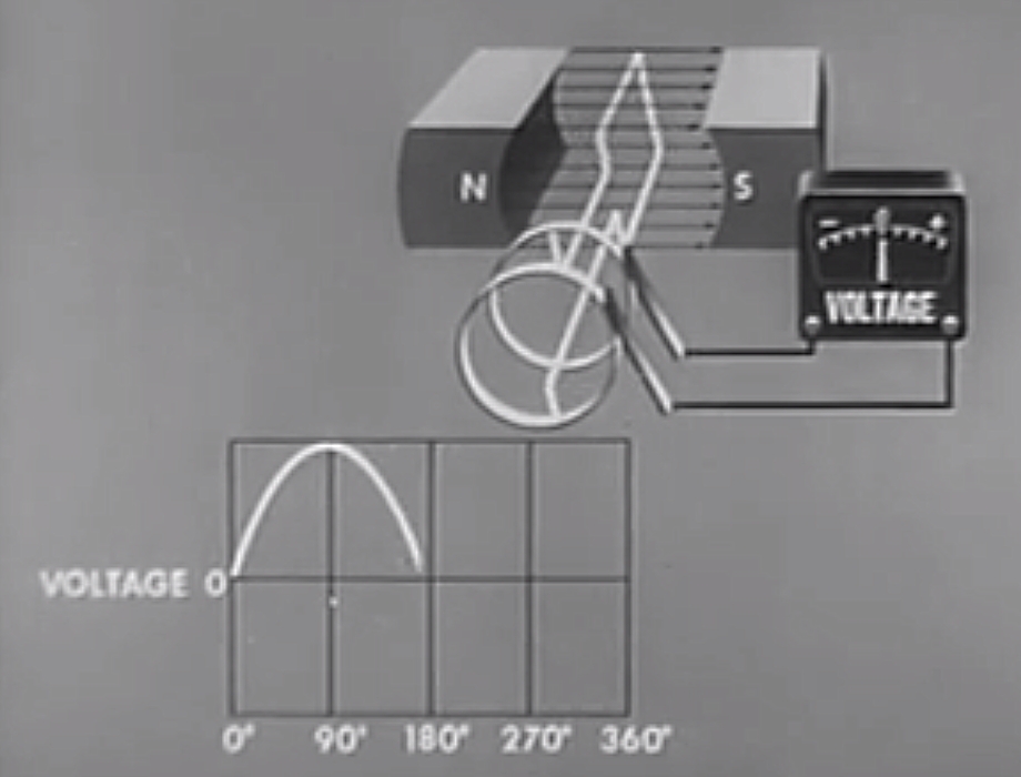
180 Degrees (\( \theta = 180^{\circ}\))
The situation at 180 degrees is similar to the situation at zero degrees. The wire is moving parallel to the magnetic field. So \( \theta = 180^{\circ} \), and the EMF is therefore zero too.
270 Degrees (\( \theta = 270^{\circ}\))
At 270 degrees of rotation, the coils are moving at their maximum speed relative to the magnetic field. It can also be said they are "cutting" the maximum number of magnetic field lines. But unlike at \( \theta = 270^{\circ} \), the coil is moving in the opposite direction. The EMF is therefore at a negative maximum, since the movement is in the opposite direction to \( \theta = 90^{\circ} \).

The direction of the induced EMF is actually the same as when \( \theta = 90^{\circ} \). However, the coil is effectively connected to the "opposite" slip rings. This reverses the orientation of the path travelled through the coil to calculate the total EMF. Because the path is in the opposite direction, the EMF is negative.
360 Degrees (\( \theta = 360^{\circ} \))
At 360 degrees, the generator has undergone one full rotation. The position is therefore the same as zero degrees, so the EMF will be the same too. The EMF will therefore be zero again.
RMS and Peak Alternator Output
Given the trickiness of determining the alternator output polarity in real time, it is generally easier to describe the RMS and peak voltages.
| With \( v \) | With \( v = r \omega \) | |
|---|---|---|
| Peak Voltage | \( \mathcal{E}_{\mathrm{pk}} = B l v \) | \( \mathcal{E}_{\mathrm{pk}} = B l r \omega \) |
| RMS Voltage | \( \mathcal{E}_{\mathrm{rms}} = \frac{B l v}{\sqrt{2}} \) | \( \mathcal{E}_{\mathrm{rms}} = \frac{B l r \omega}{\sqrt{2}} \) |
All the symbols have the same meanings as above.