Electromagnetism Resource
5. Applications and Examples
5.5. DC Generator (Dynamo)
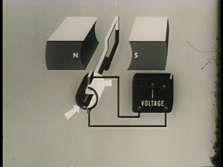
The DC generator, or dynamo is broadly similar to the AC generator, except a DC generator has a commutator instead of slip rings. The commutator acts to reverse the polarity of the generated EMF every half cycle. The voltage is converted, or rectified, from AC into pulsating DC. The figure below shows an alternator modified into a dynamo. The commutator, a segmented metal ring, is shown by the arrows.
The commutator is configured to reverse the generated AC at the zero crossings sine waveform, so the equation becomes:
\( \mathcal{E} = B l v |\sin \theta| \)
where all quantities have the same meanings as for the alternator. The \( || \) around the \( \sin \) term mean "absolute value".
We now turn our attention to an actual example. There are a series of five pictures of a single loop dynamo at 0°, 90°, 180°, 270° and 360° of rotation. The single loop coil is being turned clockwise. The upper brush is considered the positive terminal, and the lower brush the negative. The white half of the coil is connected to the white commutator segment, and the black half of the coil is connected to the black commutator segment.
Zero Degrees (\( \theta = 0^{\circ} \))
At zero degrees, the armature is moving to the right (top wire) and left (bottom wire). But the wire is moving parallel to the magnetic field. So \( \theta = 0^{\circ} \), and the EMF is therefore zero too.
The commutator brushes are in contact with both ends of the coil at once. No problems with short circuits will occur, as the generated EMF is zero at this instant.
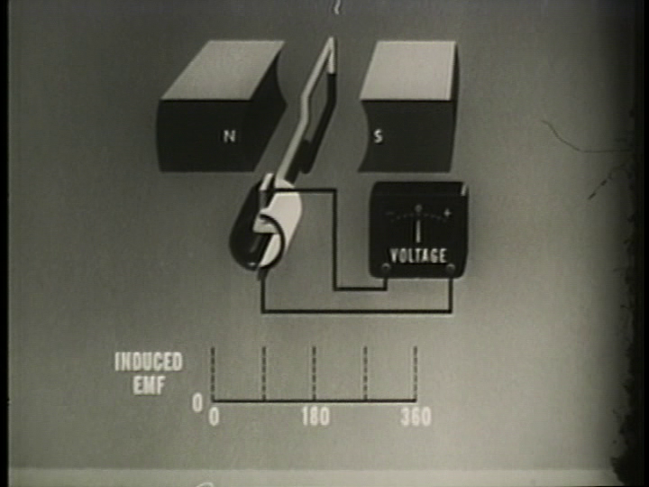
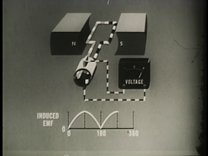
90 Degrees (\( \theta = 90^{\circ}\))
At 90 degrees of rotation, the coils are moving at their maximum speed relative to the magnetic field. It can also be said they are "cutting" the maximum number of magnetic field lines.
The EMF is therefore at a maximum, since \( \theta = 90^{\circ} \).
The relative orientations of the magnetic field and velocity will tell us whether the EMF is positive or negative at that instant.
On the right, the velocity is straight down, and the magnetic field is from left to right. Therefore, by \( \vec{E} = \vec{v} \times \vec{B} \), the electric field must be oriented towards the commutator.
On the left, the velocity is straight up, and the magnetic field is from left to right. Therefore, by \( \vec{E} = \vec{v} \times \vec{B} \), the electric field must be oriented away from the commutator.
However, because of the orientation of the path of the coil, the electric field in the wire adds up, and therefore the EMF is positive at the at the top brush relative to the bottom brush.
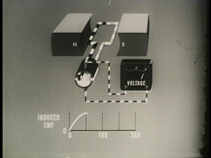
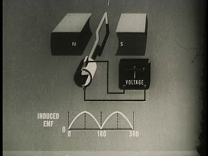
180 Degrees (\( \theta = 180^{\circ}\))
The situation at 180 degrees is similar to the situation at zero degrees. The wire is moving parallel to the magnetic field. So \( \theta = 180^{\circ} \), and the EMF is therefore zero too.
The commutator brushes are in contact with both ends of the coil at once. No problems with short circuits will occur, as the generated EMF is zero at this instant.
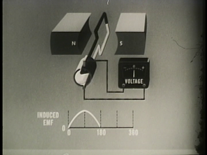
270 Degrees (\( \theta = 270^{\circ}\))
At 270 degrees of rotation, the coils are moving at their maximum speed relative to the magnetic field. It can also be said they are "cutting" the maximum number of magnetic field lines. But unlike at \( \theta = 270^{\circ} \), the coil is moving in the opposite direction. The EMF generated by the coil loop is therefore at a negative maximum, since the movement is in the opposite direction to \( \theta = 90^{\circ} \).
Because of the commutator, the induced EMF in the coil loop is at a negative maximum, but the commutator has reversed the connection (notice how the white segment is now on top). The EMF is therefore reversed, resulting in it being at a positive peak again.
360 Degrees (\( \theta = 360^{\circ} \))
At 360 degrees, the generator has undergone one full rotation. The position is therefore the same as zero degrees, so the EMF will be the same too. The EMF will therefore be zero again.
RMS, Peak and Average Dynamo Output
Given the trickiness of determining the alternator output polarity in real time, it is generally easier to describe the RMS and peak voltages.
| With \( v \) | With \( v = r \omega \) | |
|---|---|---|
| Peak Voltage | \( \mathcal{E}_{\mathrm{pk}} = B l v \) | \( \mathcal{E}_{\mathrm{pk}} = B l r \omega \) |
| RMS Voltage | \( \mathcal{E}_{\mathrm{rms}} = \frac{B l v}{\sqrt{2}} \) | \( \mathcal{E}_{\mathrm{rms}} = \frac{B l r \omega}{\sqrt{2}} \) |
| Average Voltage | \( \mathcal{E}_{\mathrm{avg}} = \frac{2 B l v}{\pi} \) | \( \mathcal{E}_{\mathrm{avg}} = \frac{2 B l r \omega}{\pi} \) |