Circuit Analysis using Modified Nodal Analysis - NEW 29 APRIL 2020
Introduction
Every electronic circuit can be analysed using nodal analysis. Nodal analysis relies on assigning a series of nodes to a circuit, then solving the voltages at each node. All circuit behaviours can be found from the nodal voltages.
Doing the 'full' Nodal Analysis requires knowledge of Linear Algebra, but the circuits will be able to be solved without using matrices, at least not directly.
We will concentrate on Modified Nodal Analysis, which uses the basic Nodal Analysis, with the additional rules below.
The circuit analysis in this course will use these seven rules:
- Ohm's Law;
- Kirchhoff's Voltage Law (KVL);
- Kirchhoff's Current Law (KCL);
- The law of resistors in series;
- The law of resistors in parallel;
- Voltage Division; and
- Current Division.
The first three rules are the general rules of Nodal Analysis. The last four rules are special cases of general Nodal Analysis, but are useful for reducing the number of variables to solve for.
Ohm's Law
See also:
- Wikipedia: https://en.wikipedia.org/wiki/Ohm%27s_law
- Wikipedia: https://en.wikipedia.org/wiki/Resistor#Ohm's_law
- Electronics Tutorials: https://www.electronics-tutorials.ws/dccircuits/dcp_2.html
Ohm's Law is the law that \( V = I R \). Ohm's Law is used to compute the voltage drop and current flow through resistors.
Kirchhoff's Voltage Law
See also:
- Wikipedia: https://en.wikipedia.org/wiki/Kirchhoff%27s_circuit_laws
- Electronics Tutorials: https://www.electronics-tutorials.ws/dccircuits/kirchhoffs-voltage-law.html
Kirchhoff's Voltage Law states that the voltages around any "loop" or "mesh" always balance between sources, and loads.
\( V_{\mathrm{source}} - V_{\mathrm{load}} = 0 \)
A loop is any circular path through a circuit.
Kirchhoff's Current Law
See also:
- Wikipedia: https://en.wikipedia.org/wiki/Kirchhoff%27s_circuit_laws
- Electronics Tutorials: https://www.electronics-tutorials.ws/dccircuits/kirchhoffs-current-law.html
Kirchhoff's Current Law states that the currents at any node always balance between incoming and outgoing currents.
\( I_{\mathrm{in}} - I_{\mathrm{out}} = 0 \)
Series Resistors
See also:
- Wikipedia: https://en.wikipedia.org/wiki/Series_and_parallel_circuits
- Wikipedia: https://en.wikipedia.org/wiki/Resistor#Series_and_parallel_resistors
- Electronics Tutorials: https://www.electronics-tutorials.ws/resistor/res_3.html
Resistors in series always have the same current passing through them. This means that the total voltage drop across the series combination of resistors is the same as the sum of the voltage drop across each resistor individually.
The derivation of the series resistance formula comes from Ohm's Law.
\( R_{\mathrm{TOT}} = R_1 + R_2 + \cdots \)
Parallel Resistors
See also:
- Wikipedia: https://en.wikipedia.org/wiki/Series_and_parallel_circuits
- Wikipedia: https://en.wikipedia.org/wiki/Resistor#Series_and_parallel_resistors
- Electronics Tutorials: https://www.electronics-tutorials.ws/resistor/res_4.html
Resistors in parallel always have the same voltage across them them. This means that the total current through the set of parallel resistors is the same as the current slow through the parallel combination of resistors is the same as the sum of the current flow through each resistor individually.
\( \frac{1}{R_{\mathrm{tot}}} = \frac{1}{R_1} + \frac{1}{R_2}+ \cdots \)
Voltage Division (Voltage Divider)
See also:
- Wikipedia: https://en.wikipedia.org/wiki/Voltage_divider
- Electronics Tutorials: https://www.electronics-tutorials.ws/dccircuits/voltage-divider.html
Voltage division takes advantage of two behaviours of series resistors:
- the current through each resistor is the same; and
- the total voltage across a set of series resistors is the sum of the voltage across each resistor.
The equation for the voltage drop across a given resistor \( R_m \) in a series circuit is given by:
\( V_m = V \cdot \frac{R_m}{R_{\mathrm{TOT}}} \)
where \( V_m \) is the voltage drop across resistor \( R_m \), V is the total voltage across the series combination of resistors, \( R_m \) is the resistance value of resistor \( R_m \), and \( R_{\mathrm{TOT}} \) is the total series resistance of the set of series resistors.
Current Division (Current Divider)
See also:
- Wikipedia: https://en.wikipedia.org/wiki/Current_divider
- Electronics Tutorials: https://www.electronics-tutorials.ws/dccircuits/current-divider.html
Current division takes advantage of two behaviours of parallel resistors:
- the voltage drop across each resistor is the same; and
- the total current through a set of parallel resistors is the sum of the current through each resistor.
The equation for the current through a given resistor \( R_m \) in a parallel circuit is given by:
\( I_m = I \cdot \frac{R_{\mathrm{TOT}}}{R_m} \)
where \( I_m \) is the current through resistor \( R_m \), I is the total current through the parallel combination of resistors, \( R_m \) is the resistance value of resistor \( R_m \), and \( R_{\mathrm{TOT}} \) is the total parallel resistance of the set of parallel resistors.
Step 1: Identify the Nodes
The first step is to analyse the circuit, and identify all the nodes.
Every circuit must have a reference or ground node, that serves as the reference for all the other voltages. I assign the ground node node 0. The ground node is always assigned negative to any other nodes (e.g. if you were measuring the voltage, the black lead always goes on ground).
The other nodes can be identified using letters, numbers or any other suitable scheme. The node voltage \( V_n \) is always relative to the ground node.
The voltage between two nodes \( m \) and \( n \) is denoted by putting the two nodes in the subscript e.g. \( V_{mn} \). The node that comes first is considered positive, the second is considered negative. If you were measuring \( V_{mn} \), you would put the positive lead of your multimeter at node m, and the negative at node n.
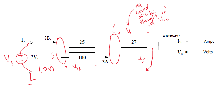
Assign a polarity to voltage sources. The negative terminal is usually connected to ground. An example is shown below. The example is Question 1 from Worksheet 16A: Harder Series-Parallel Calculations.

The ground node has been assigned as the negative terminal of the supply voltage.
I have created two nodes, called 's', and '1'. The voltage \( V_{\mathrm{s}} \) is also the same as the supply voltage.
Step 2: Identify Any Constraints
Some circuits may already have fixed values of voltage or current. These can be factored into the Kirchhoff's Law solutions of the circuit.

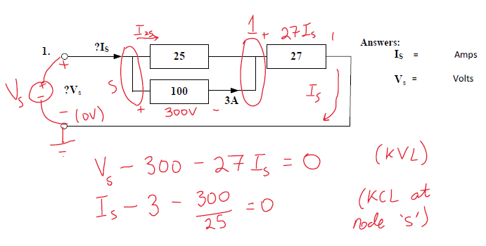
In the case of the example, we have the following constraints:
- the current through the 100 Ω resistor is 3 A (information given at start of problem);
- the voltage across the 100 Ω resistor (\( V_{\mathrm{s1}} \)) must be 300V with the polarity shown (Ohm's Law);
- the voltage across the 25 Ω resistor must be \( V_{\mathrm{s1}} \) (parallel circuits have an equal voltage across all components);
- the voltage across the 25 Ω resistor must be 300V with the polarity shown (\( V_{\mathrm{s1}} = 300 \));
- the current flow through the 25 Ω resistor (\( I_{25} \) must be 12 A in the direction shown (Ohm's Law);
- the voltage drop across the 27 Ω resistor must be \( 27 \cdot I_{\mathrm{s}} \) with the polarity shown (Ohm's Law).
The current constraint also fixes the voltage across the resistor at 300 V, by Ohm's Law. In other words, \( V_{\mathrm{s1}} = 300 \).
Step 3: Create Kirchhoff's Law Equations
Since we have identified all the nodes, and constraints, we can formulate the Kirchhoff's Voltage Law and Kirchhoff's Current Law equations. NOTE: In a circuit with \( n \) unknowns, there must be \( n \) equations.

Kirchhoff's Voltage Law
Kirchhoff's Voltage Law involves traversing all the loops in the circuit. If the loop direction is going from negative to positive, the voltage is considered to be additive. If the direction of traverse goes from positive to negative the voltage is considered to be subtractive.
For the example, we traverse the circuit starting at the negative terminal of \( V_{\mathrm{s}} \) and going clockwise. Going clockwise is convenient, as it makes the supply voltage positive in the equation immediately. Traversing the loop gives us the equation below.
\( V_{\mathrm{s}} - (V_{\mathrm{s}} - V_{\mathrm{1}}) - V_{\mathrm{1}} = V_{\mathrm{s}} - 300 - 27 I_{\mathrm{s}} = 0 \)
where the quantity 300 comes from the constraint that \( V_{\mathrm{s}} - V_{\mathrm{1}}\) is 300 V due to the constrained voltage across the 100 Ω resistor; and \( 27 I_{\mathrm{s}} \) is the voltage drop across the 27 Ω resistor.
Kirchhoff's Current Law
Kirchhoff's Current Law involves 'balancing' the incoming and outgoing currents at every node except the ground node.
If a current is 'entering' a node, it is given a positive sign in the equation. If the current is 'leaving' the node, it is given a negative sign.
NOTE: A current that leaves at one node must enter another node.
For the example circuit, we get two Kirchhoff's Current Law equations:
At node 's': \( I_{\mathrm{s}} - 3 - \frac{300}{25} = I_{\mathrm{s}} - 3 - 12 = 0 \)
At node '1': \( 3 + \frac{300}{25} - I_{\mathrm{s}} = 3 + 12 - I_{\mathrm{s}} \)
Notice how \( I_\mathrm{s} \) is entering node 's', and leaving node '1'. The quantity \( 3 \) is the current flowing through the 100 Ω resistor. The quantity \( \frac{300}{25} \) is the current flowing through the 25 Ω resistor. Notice that the equation for node '1' is the negative of the equation for node 's'. We can eliminate one of them, as having two of them does not reveal any new information.
Step 4: Simplify and Solve the Kirchhoff's Law Equations
We have two equations to solve. These are simultaneous equations.

There are many techniques of solving simultaneous equations, but the one we will concentrate on is back-substitution.
KVL: \( V_{\mathrm{s}} - 300 - 27 I_{\mathrm{s}} = 0 \)
KCL at node 's': \( I_{\mathrm{s}} - 15 = 0 \)
Look for the equation with one unknown. In out case, it's the KCL equation at node 's'.
Solving this gives us \( I_{\mathrm{s}} \) = 15 A.
We can substitute this into the KVL equation to solve for \( V_{\mathrm{s}} \).
KVL: \( V_{\mathrm{s}} - 300 - 27 \cdot 15 = 0 \rightarrow V_{\mathrm{s}} - 705 = 0 \rightarrow V_{\mathrm{s}} = 705 \)
So \( I_{\mathrm{s}} \) = 15 A, and \( V_{\mathrm{s}} \) = 705 V.
Example 2: Worksheet 15A, Q2
Worksheet 15A, Q2 is a more complex example due to its mixture of series and parallel circuits.
First, we identify the nodes and the constraints. The only constraint is that \( V_{\mathrm{s}} \) (as identified using the nodes below) must be 159 V.

The additional variables \( I_{\mathrm{s}} \) and \( I_{18} \) represent the supply current and the current through the 18 Ω resistor respectively. Some further analysis using the parallel resistance formulas gives the circuit below.

The circuit above allows us to formulate a Kirchhoff's Voltage Law equation that only involves \( I_{\mathrm{s}} \). Once we have \( I_{\mathrm{s}} \), we can calculate all the rest of the currents. The equations to solve the circuit are shown below.
- EQ1: \( 159 - (12.6 + 50 + \frac{10}{3}) I_{\mathrm{s}} \rightarrow 159 - \frac{989}{15} I_{\mathrm{s}}= 0 \) (Kirchhoff's Voltage Law)
- EQ2: \( I_{42} = \frac{12.6}{42} I_{\mathrm{s}} \) (Current Division at node 's')
- EQ3: \( I_{10} = \frac{1}{3} I_{\mathrm{s}} \) (Current Division at node '1')
Equation EQ1 can be solved first, because it has one unknown only. Equations EQ2 and EQ3 can then be solved by back-substitution.
Solving EQ1 yields \( I_{\mathrm{s}} = 159 \cdot \frac{15}{989} \) = 2.412 A.
Back-substituting \( I_{\mathrm{s}} \) into EQ2 and EQ3 yields \( I_{42} \) = 0.7236 A and \( I_{10} \) = 0.8040 A.