Worksheet 9A - Internal Resistance of a power supply - Solutions and Commentary
Introduction
The voltage drop when a power supply (in this case a battery) is placed under load can be modelled as the effect of an internal resistance.
The power supply has an internal EMF, which is the "no-load" (\( I_{\mathrm{L}} = 0 \)) voltage. Load current will cause a voltage drop across the internal resistance, lowering the voltage seen at the supply terminals.
The effect of the internal resistance may be modelled using voltage division, using the internal resistance, and the total resistance.
Calculations using Voltage Division
The general formula for supply voltage with internal resistance is as follows:
\( V_{\mathrm{s}} = \mathcal{E} \cdot \frac{R_{\mathrm{L}}}{R_{\mathrm{L}} + R_{\mathrm{Int}}} \)
where \( V_{\mathrm{s}} \) is the supply voltage seen at the supply terminals, \(\mathcal{E} \) is the internal EMF of the power supply, \( R_{\mathrm{L}} \) is the total load resistance, and \( R_{\mathrm{Int}} \) is the internal resistance of the power supply.
It is not possible to measure \( R_{\mathrm{Int}} \) directly, as it is not possible to separate it from the EMF generating mechanism (e.g. in a battery the electrolyte may contribute a resistive effect at the same time as it assists generating the EMF).
The theoretical method of measuring \( R_{\mathrm{Int}} \) is given by the formula below.
\( R_{\mathrm{Int}} = \frac{V_{\mathrm{oc}}}{I_{\mathrm{sc}}} \)
where \( R_{\mathrm{Int}} \) is the internal resistance, \( V_{\mathrm{oc}} \) is the open-curcuit voltage (no-load voltage), and \( I_{\mathrm{sc}} \) is the short-circuit current. This method is generally not used on real sources, since the short circuit current is often dangerously high. Further, many power supplies (especially current-limited power supplies) have a value of \( R_{\mathrm{Int}} \) that depends on the load current. Most methods of measuring \( R_{\mathrm{Int}} \) rely on measuring the voltage drop for a known load current.
The internal voltage drop is given in the equation below.
\( V_{\mathrm{Int}} = \mathcal{E} - V_{\mathrm{s}} \)
where \( V_{\mathrm{Int}} \) is the internal voltage drop, and \( \mathcal{E} \) and \( V_{\mathrm{s}} \) have the same meanings as above.
Calculations using Load Current
If the load current is known, the calculations can be simplified.
The general formula for supply voltage with internal resistance is as follows:
\( V_{\mathrm{s}} = \mathcal{E} - I_{\mathrm{L}} R_{\mathrm{Int}} \)
where \( V_{\mathrm{s}} \) is the supply voltage seen at the supply terminals, \(\mathcal{E} \) is the internal EMF of the power supply, \( I_{\mathrm{L}} \) is the load current, and \( R_{\mathrm{Int}} \) is the internal resistance of the power supply.
It is not possible to measure \( R_{\mathrm{Int}} \) directly, as it is not possible to separate it from the EMF generating mechanism (e.g. in a battery the electrolyte may contribute a resistive effect at the same time as it assists generating the EMF).
The theoretical method of measuring \( R_{\mathrm{Int}} \) is given by the formula below.
\( R_{\mathrm{Int}} = \frac{\mathcal{E} - V_{\mathrm{s}}}{I_{\mathrm{L}}} \)
where \( R_{\mathrm{Int}} \) is the internal resistance, and all other symbols have the same meanings as above.
\( R_{\mathrm{Int}} = I_{\mathrm{L}} R_{\mathrm{Int}} \)
where \( V_{\mathrm{Int}} \) is the internal voltage drop, and all other symbols have the same meanings as above.
Question 1
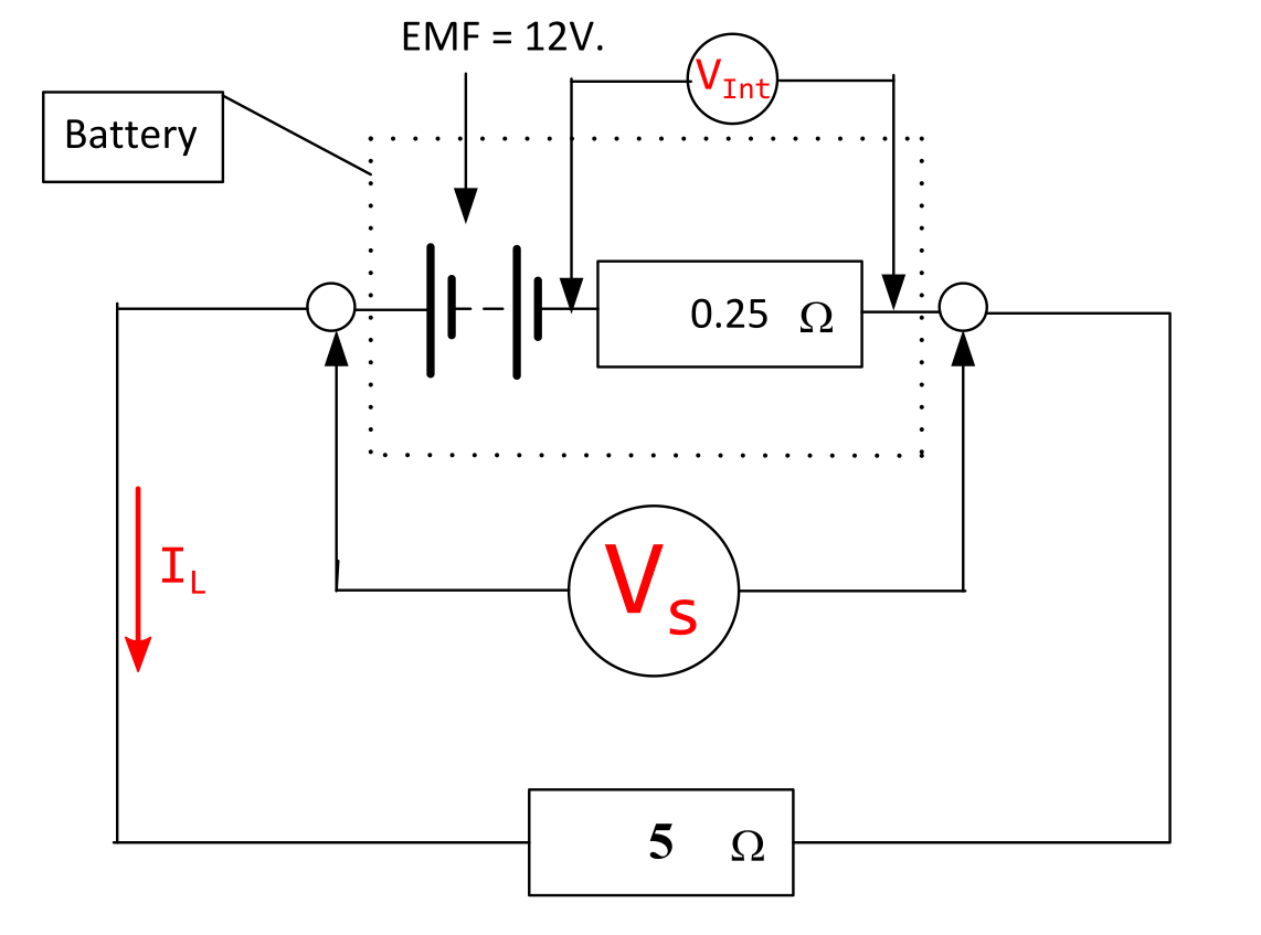
A battery has an EMF of 12 V and an internal resistance of 0.25 Ohms. Find the drop in voltage across the battery output terminals when a load of 5 Ohms is applied and the battery output Voltage.
The marked-up schematic is shown below.

Solution - Load Current
\( I_{\mathrm{L}} = \frac{\mathcal{E}}{R_{\mathrm{L}} + R_{\mathrm{Int}}} = \frac{12}{5 + 0.25} = \frac{12}{5.25} = \) 2.28571 A (6 sf).
\( V_{\mathrm{s}} = I_{\mathrm{L}} R_{\mathrm{L}} = 2.28571 \cdot 5 = \) 11.43 V (4 sf).
\( V_{\mathrm{Int}} = I_{\mathrm{L}} R_{\mathrm{Int}} = 2.28571 \cdot 0.25 = \) 0.57 V (2 dp).
Solution - Voltage Division
\( V_{\mathrm{s}} = \mathcal{E} \cdot \frac{R_{\mathrm{L}}}{R_{\mathrm{L}} + r} = 12 \cdot \frac{5}{5 + 0.25} = 12 \cdot 0.952381 = \) 11.4286 V (6 sf) or 11.43 V (4 sf) #.
The voltage drop across the internal resistance is the difference between the internal EMF, and the load voltage.
\( V_{\mathrm{Int}} = \mathcal{E} - V_{\mathrm{s}} = 12 - 11.4286 = \) 0.57 V (2 dp) #.
Question 2
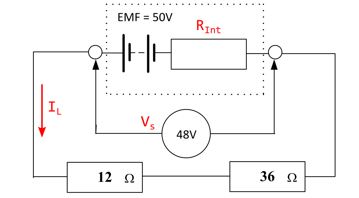
Determine the value of the internal resistance.
The marked-up schematic is shown below.

Solution - Load Current
\( I_{\mathrm{L}} = \frac{V_{\mathrm{s}}}{R_{\mathrm{L}}} = \frac{48}{12 + 36} = \) 1 A .
\( R_{\mathrm{Int}} = \frac{\mathcal{E} - V_{\mathrm{s}}}{I_{\mathrm{L}}} = \frac{50 - 48}{1} = \) 2 Ω.
Solution - Voltage Division
\( V_{\mathrm{s}} = \mathcal{E} \cdot \frac{R_{\mathrm{L}}}{R_{\mathrm{L}} + R_{\mathrm{Int}}} \rightarrow R_{\mathrm{Int}} = R_{\mathrm{L}} \cdot \frac{\mathcal{E} - V_{\mathrm{s}}}{V_{\mathrm{s}}} \)
\( R_{\mathrm{Int}} = R_{\mathrm{L}} \cdot \frac{\mathcal{E} - V_{\mathrm{s}}}{V_{\mathrm{s}}} = 48 \cdot \frac{50 - 48}{48} = 48 \cdot \frac{2}{48} = \) 2 Ω.
Question 3
Ten 1.5V cells are connected in series. Each cell has an internal resistance of 0.15 Ohms. What would be the Voltage across a 6 Ohm load resistor placed across the complete battery?
The supply arrangement is as follows:
- There are ten 1.5 V cells in series → \( \mathcal{E} = \) 15 V.
- Each of the ten cells has an internal resistance of 0.15 Ω → \( R_{\mathrm{Int}} = \) 1.5 Ω.
The load resistance is 6 Ω.
A marked-up schematic is shown below.

Solution - Load Current
\( I_{\mathrm{L}} = \frac{\mathcal{E}}{R_{\mathrm{L}} + R_{\mathrm{Int}}} = \frac{15}{6 + 1.5} = \) 2 A .
\( V_{\mathrm{s}} = I_{\mathrm{L}} R_{\mathrm{L}} = 6 \cdot 2 = \) 12 V.
Solution - Voltage Division
\( V_{\mathrm{s}} = \mathcal{E} \cdot \frac{R_{\mathrm{L}}}{R_{\mathrm{L}} + R_{\mathrm{Int}}} = 15 \cdot \frac{6}{6 + 1.5} = \) 12 V #.
There is no need to calculate the internal voltage drop, but for the record it is 3 V.